

Filter
a filter and filter body technology, applied in the field of filters, can solve the problems of low degree of freedom in the design stage of filters, too complicated patterns to reduce the size of filters, etc., and achieve the effect of simple structure and higher degree of freedom in design
- Summary
- Abstract
- Description
- Claims
- Application Information
AI Technical Summary
Benefits of technology
Problems solved by technology
Method used
Image

Examples
first embodiment
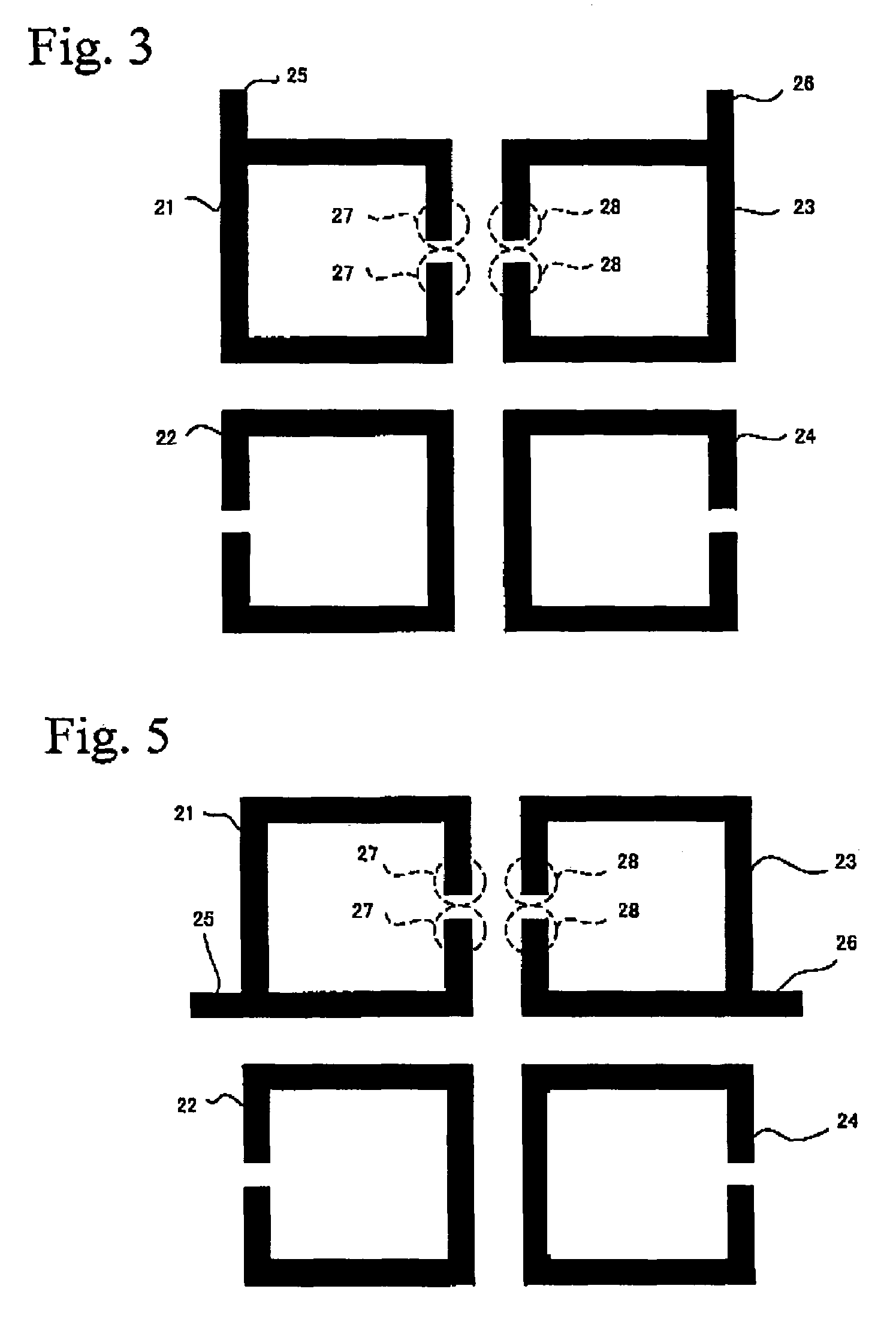
[0028]FIG. 3 illustrates a filter in accordance with a first embodiment of the present invention. The filter shown in FIG. 3 includes four microstrip lines 21, 22, 23, and 24, and two input / output terminals 25 and 26. These patterns are formed on a dielectric substrate having a ground pattern formed on the back. Each of the microstrip lines 21 through 24 is an open-looped transmission path that is substantially equivalent to ½ of the wavelength λ corresponding to the center frequency of the pass band or a frequency in the neighborhood of the center frequency. So as to form an open loop, each of the microstrip lines 21 through 24 has four bent portions. Having loop-like forms, the microstrip lines 21 through 24 can be arranged in a relatively small area. The microstrip lines 21 and 22 are arranged to provide hybrid coupling by combining capacitive coupling and inductive coupling, the microstrip lines 22 and 24 are arranged to provide inductive coupling, and the microstrip lines 24 an...
second embodiment
[0034]FIGS. 7A through 7D each illustrate a filter in accordance with a second embodiment of the present invention. The filters shown in FIGS. 7A through 7D use microstrip lines as transmission paths but have different resonator structures from one another. Each of the filters includes microstrip lines 31 and 32 of λ / 2 in length, and input / output terminals 34 and 35 that are provided for the microstrip lines 31 and 32, respectively. The microstrip lines 31 and 32 and the input / output terminals 34 and 35 are formed on a dielectric substrate that is indicated by a broken line in each of FIGS. 7A through 7D. A resonator that is described below is interposed between the microstrip lines 31 and 32 in each of the filters. The resonator is coupled to the microstrip line 31 so that the microstrip line 31 has open stubs in which the connection point between the input / output terminal 34 and the microstrip line 31 appears to be short-circuited when seen from the ends of the microstrip line 31....
third embodiment
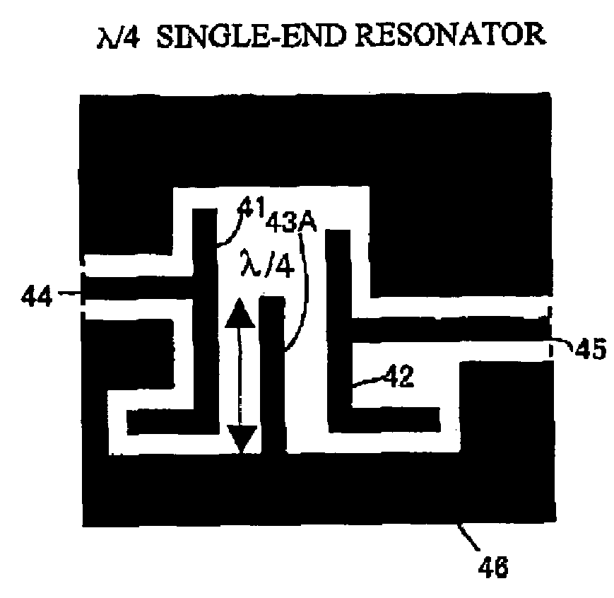
[0036]FIGS. 8A through 8C each illustrate a filter in accordance with a third embodiment of the present invention. The filters shown in FIGS. 8A through 8C use coplanar lines as transmission lines but have different resonator structures from one another. Each of the filters includes line patterns 41 and 42 of λ / 2 in length, and input / output terminals 44 and 45 that are provided for the line patterns 41 and 42, respectively. The line patterns 41 and 42 and the input / output terminals 44 and 45 are formed on a dielectric substrate that is indicated by a broken line in each of FIGS. 8A through 8C. A ground pattern 46 is also provided so as to surround both ends of each of the line patterns 41 and 42, thereby forming a coplanar line structure. A resonator that is described below is interposed between the line patterns 41 and 42 in each of the filters. The resonator is coupled to the line pattern 41 so that the line pattern 41 has open stubs in which the connection point between the input...
PUM
 Abstract
Description
Claims
Application Information