
Heat exchange system

a technology of heat exchange system and tank system, which is applied in the direction of heating types, lighting and heating apparatus, instruments, etc., can solve the problems of large floor space, waste of energy to heat unused water, slow reaction speed of the tank system, etc., and achieve the effect of reducing heat deflection

Active Publication Date: 2007-10-09
MORTARA INSTR +1
View PDF6 Cites 4 Cited by
  • Summary
  • Abstract
  • Description
  • Claims
  • Application Information

AI Technical Summary

Benefits of technology

"The invention is an improved shell-and-tube steam-fired instantaneous heat exchange system that overcomes various limitations of existing systems. It is designed to provide a wide range of outlet temperatures for different flow rates, act quickly in response to changes in demand, have built-in redundancy, occupy minimal floor space, not waste energy, and provide safety features. The system includes a first and second process heat exchanger, a water circulating circuit, and a secondary heat exchanger for preheating the cold water. The system also has a temperature limiting device and a rigid support frame for stabilizing the heat exchangers. The technical effects of the invention include improved efficiency, faster response time, reduced risk of scalding, and reduced floor space requirements."

Problems solved by technology

Thus, although they can supply a large volume of water, bulky tank systems are slow to react and waste energy to heat unused water.
They also tend to require a large amount of floor space to accommodate the storage tank.
Maintaining a leaking tank is expensive and replacement often involves tearing out walls of the surrounding structure.

Method used


Image

  • Heat exchange system
  • Heat exchange system
  • Heat exchange system

Examples


Embodiment Construction

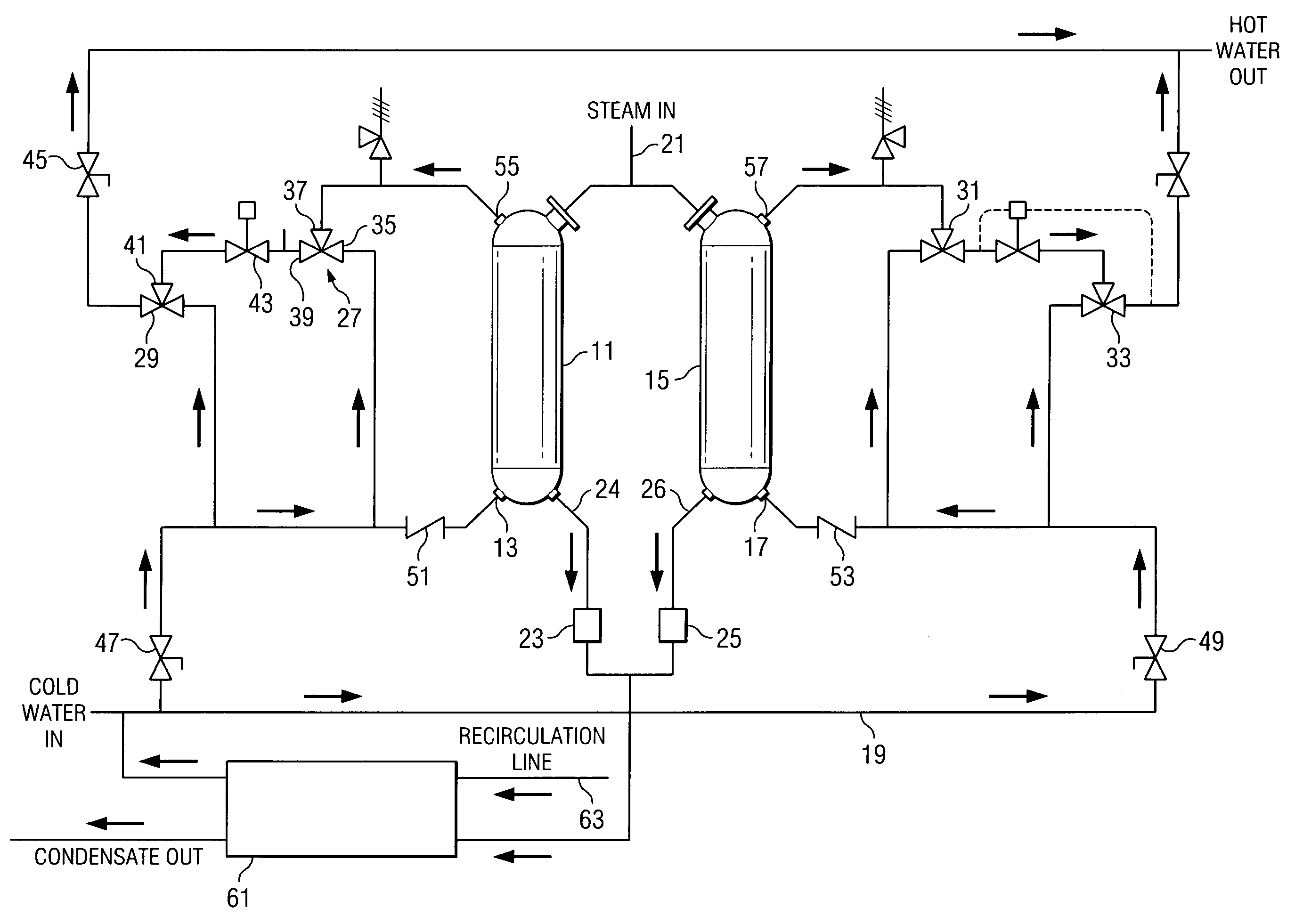
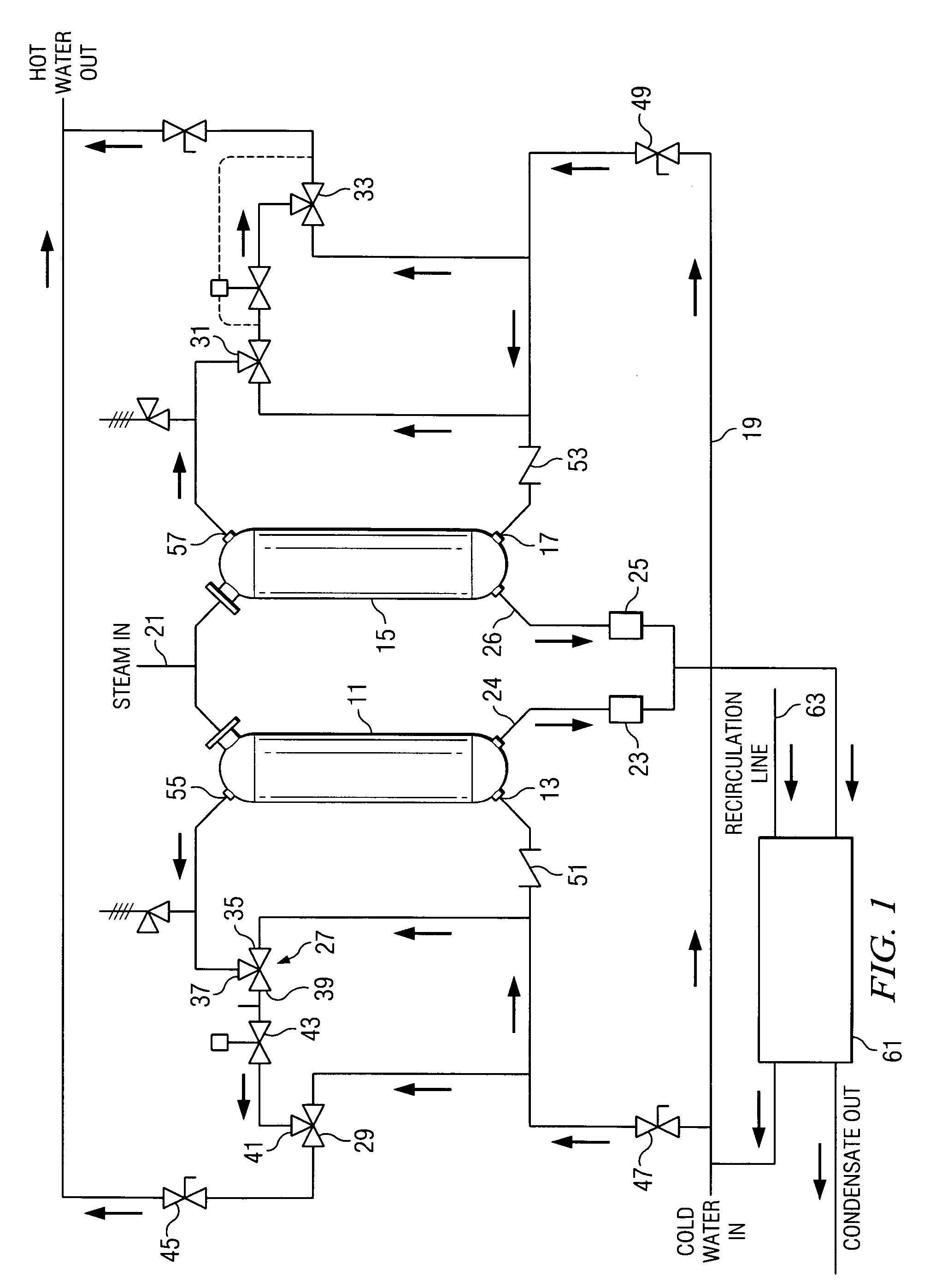
[0041]FIG. 1 is a schematic diagram illustrating the operational flow of the heat exchange system of the invention. In one embodiment, this instantaneous water heater system utilizes steam from a local boiler or district plant to provide energy to heat water up to a desired temperature for a variety of hot water end use applications. The water temperature control scheme which is illustrated in FIG. 1 and which will be described in greater detail herein operates with equal precision whether hot water or another hot fluid is used as the energy source to heat the process water up the desired end use temperature, or whether steam is utilized as the energy source.

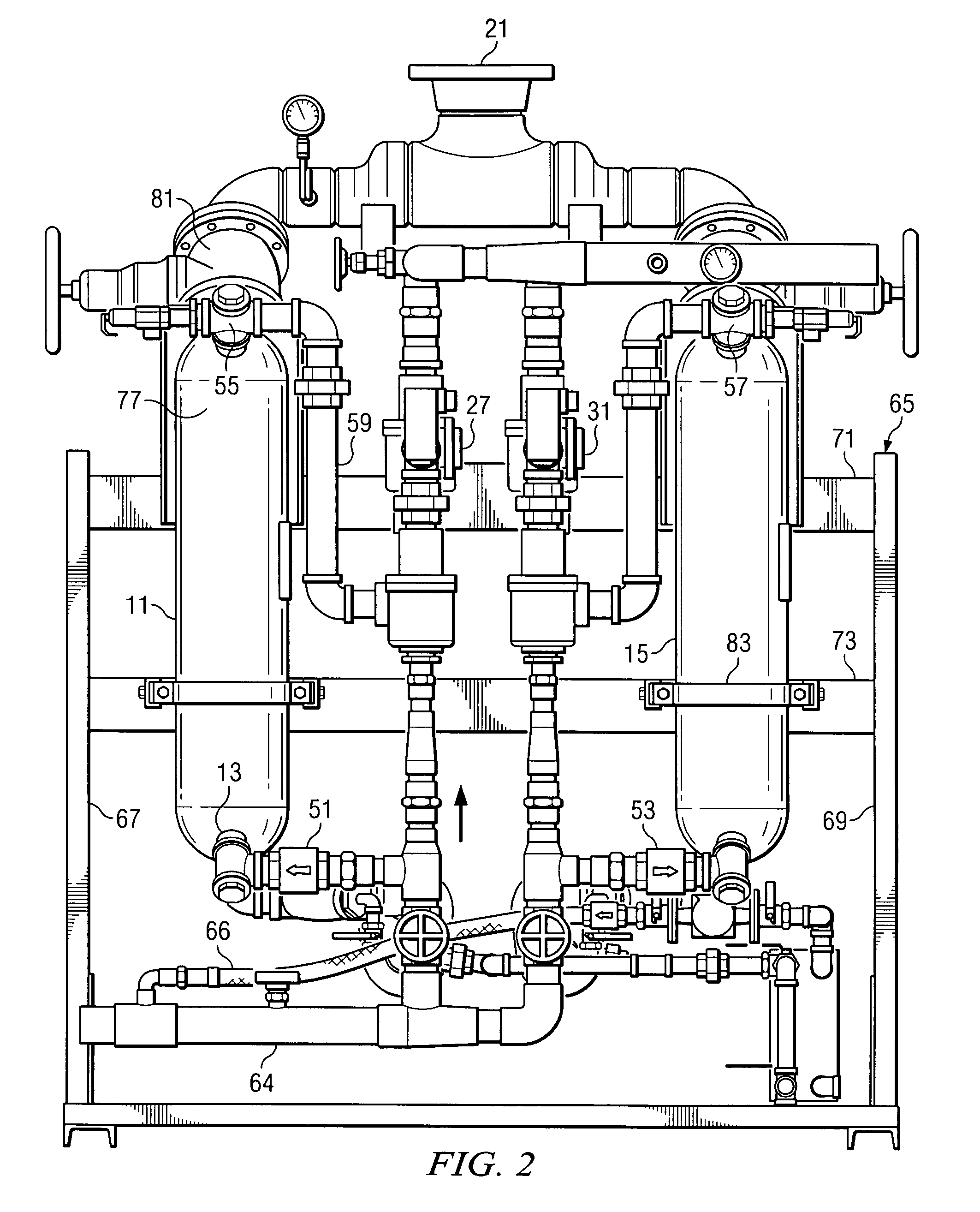
[0042]The basic building blocks of the heat exchange system are a first process shell-and-tube 11 having a cold water inlet 13. Preferably, at least a second process shell-and-tube heat exchanger 15 is provided also having a cold water inlet 17 and being mounted in water circulating circuit 19 in parallel fashion with the first ...


PUM


Abstract

An improved shell-and-tube steam instantaneous heat exchange system of a closely coupled feedback design which overheats water in the heat exchanger portion of the system and then blends the water, as needed, with proportional amounts of cold water to achieve the correct outlet temperature for a wide range of flow rates. The system uses at least two primary heat exchangers to provide redundancy in the case of failure of a major component of the system. Steam flow through the heat exchangers is controlled by the use of steam traps, rather than using a thermostatically controlled valve to vary the supply of steam. To obtain precise temperature control during varying water volume use, water is directed from the blended outlet of a first water tempering valve into the hot inlet port of a second water tempering valve. The first valve is designed to blend cold and hot water to a predetermined temperature which is higher than the second water tempering valve, so as to bias the second tempering valve, thereby minimizing thermal hunting and providing tighter temperature control from the second tempering valve.

Description

BACKGROUND OF THE INVENTION[0001]A. Field of the Invention[0002]This invention relates in general to heat exchange systems and, in particular, to an instantaneous steam fired water heater system.[0003]B. Description of the Prior Art[0004]Water heaters are used in a large variety of residential, commercial and industrial settings. For example, large storage tank systems are often found in hospitals and institutions, industrial plants, schools, universities, apartment complexes, and the like. The different types of water heaters which are used to supply hot water to these systems may use various sources of energy, such as gas, oil, electricity or steam. For example, in conventional gas / oil fired water heaters, hot gas flows through a series of vertically mounted tubes which are mounted in vertical fashion between top and bottom support plates within the water heater tank. Water flows into and out of a chamber located between the support plates and contacts and circulates about the ext...

Claims


Application Information

Patent Timeline
Patent Type & Authority Patents(United States)
IPC IPC(8): F24D19/00
CPCF24D1/005F28F9/007F28F9/26F28F2265/00Y02B30/16Y02B30/00Y02P80/10
Inventor PECKHAM, JOHN M.MYERS, FRANK A.BOLLAS, CHRISTOPHER J.
Owner MORTARA INSTR
Learn More