Solid-oxide fuel cell system having an integrated air/fuel manifold

a fuel cell and air/fuel manifold technology, applied in the field of hydrogen/oxygen fuel cells, can solve the problems of high cost, large size, complexity, moderate reliability, and large size of the connection, and achieve the effect of convenient and inexpensive formation

Active Publication Date: 2007-10-09
APTIV TECH LTD
View PDF23 Cites 15 Cited by
  • Summary
  • Abstract
  • Description
  • Claims
  • Application Information

AI Technical Summary

Benefits of technology

[0009]Briefly described, in a solid-oxide fuel cell system, a compact, highly space-efficient basal manifold conveys high temperature air, exhaust, and hydrogen-rich fuel such as, for example, reformate or pure hydrogen, to and from the core components of the system. The manifold is a three-dimensional assembly of plates and shallow partitioned elements which

Problems solved by technology

These components often have welded or compression-fitting connections that have the undesirable characteristics of high cost, large size, complexity, and moderate reliability.
In

Method used


Image

  • Solid-oxide fuel cell system having an integrated air/fuel manifold
  • Solid-oxide fuel cell system having an integrated air/fuel manifold
  • Solid-oxide fuel cell system having an integrated air/fuel manifold

Examples


Embodiment Construction

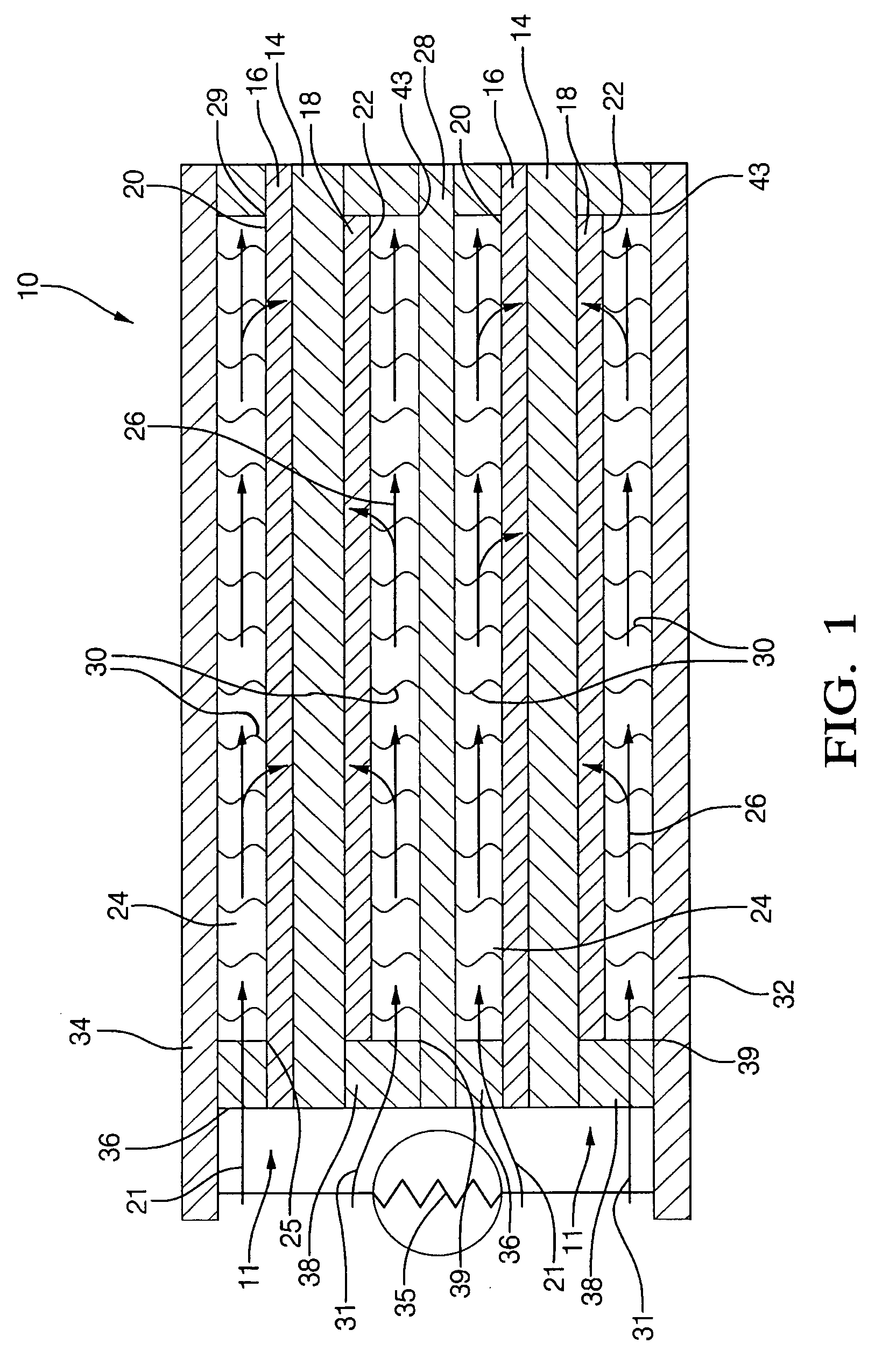
[0029]Referring to FIG. 1, a fuel cell stack 10 includes elements known in the art of solid-oxide fuel cell stacks comprising more than one fuel cell. The example shown includes two identical fuel cells 11, connected in series, and is of a class of such fuel cells said to be “anode-supported” in that the anode is a structural element having the electrolyte and cathode deposited upon it. Element thicknesses as shown are not to scale.

[0030]Each fuel cell 11 includes an electrolyte element 14 separating an anodic element 16 and a cathodic element 18. Each anode and cathode is in direct chemical contact with its respective surface of the electrolyte, and each anode and cathode has a respective free surface 20,22 forming one wall of a respective passageway 24,26 for flow of gas across the surface. Anode 16 of one fuel cell 11 faces and is electrically connected to an interconnect 28 by filaments 30 extending across but not blocking passageway 24. Similarly, cathode 18 of fuel cell 11 fac...


PUM


Abstract

A solid-oxide fuel cell system having a compact, highly space-efficient basal manifold for conveying high temperature air, exhaust, and hydrogen-rich reformate fuel to and from the core components of the system. The manifold is a three-dimensional assembly of plates and partitioned elements which are easily and inexpensively formed. When assembled, the manifold comprises a network of passageways which allow for the mounting, close-coupling, and integration of critical fuel cell system components, including heat exchangers, a tail gas combustor and fuel reformer, solid-oxide fuel cell stacks, check valves, and oxygen scavengers.

Description

TECHNICAL FIELD[0001]The present invention relates to hydrogen / oxygen fuel cells having a solid-oxide electrolytic layer separating an anode layer from a cathode layer; more particularly, to fuel cell assemblies comprising a plurality of individual fuel cells in a stack wherein air and reformed fuel are supplied to the stack; and most particularly, to a fuel cell system including an on-board hydrocarbon reformer, waste energy recovery assembly including a spent fuel burner and heat exchangers, an air supply assembly, and a control system, wherein a three-dimensional basal manifold having formed ports and passageways both supports and interconnects all of these functions.BACKGROUND OF THE INVENTION[0002]Fuel cells which generate electric current by the electrochemical combination of hydrogen and oxygen are well known. In one form of such a fuel cell, an anodic layer and a cathodic layer are separated by an electrolyte formed of a ceramic solid oxide. Such a fuel cell is known in the ...

Claims


Application Information

Patent Timeline
IPC IPC(8): H01M8/02B60L11/18H01M8/04H01M8/06H01M8/12H01M8/24H01M10/44
CPCH01M8/0618H01M8/2425H01M8/2465H01M8/2475H01M8/249H01M8/2485H01M8/04022Y02E60/525H01M2008/1293H01M2250/20Y02T90/32Y02E60/50H01M8/2432H01M8/2484Y02T90/40
Inventor KELLY, SEAN M.HALTINER, JR., KARL J.DEMINCO, CHRISTOPHER M.
Owner APTIV TECH LTD
Why Eureka
Try Eureka