Low friction fabric

Inactive Publication Date: 2007-10-16
DATA TRACE PUBLISHING
View PDF8 Cites 18 Cited by
  • Summary
  • Abstract
  • Description
  • Claims
  • Application Information

AI Technical Summary

Benefits of technology

[0021]Additionally, the present invention would have a tremendous impact on wound dressing devices. Plastic surgeons and those treating burns and ulcers require frictionless bandaging systems to reduce the level of mechanical stress on the superficial skin structures. Standard dressings, which adhere to a wound, can easily disrupt new skin grafts or cause deeper injuries to slowly healing wounds by shearing the layers of skin. A frictionless system would allow the patient greater mobility by allowing movement, even adjacent to bony prominences and joints
[0022]Th

Problems solved by technology

Peripheral sensory neuropathy reduces a person's ability to feel their feet.
These individuals do not have the ability to detect when their skin has been inj

Method used


Image

  • Low friction fabric
  • Low friction fabric
  • Low friction fabric

Examples


Example

EXAMPLE I

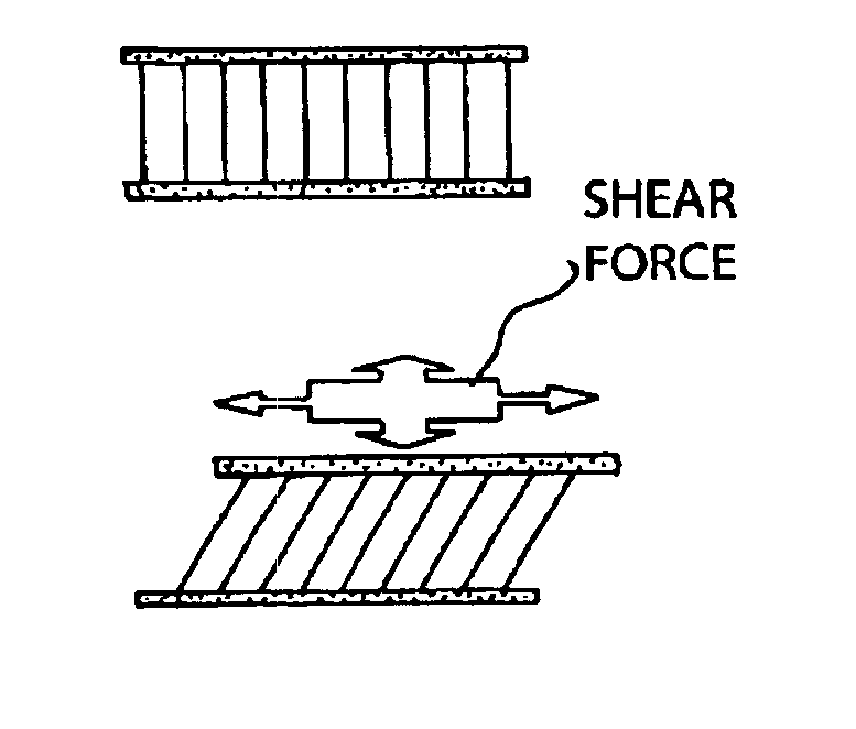
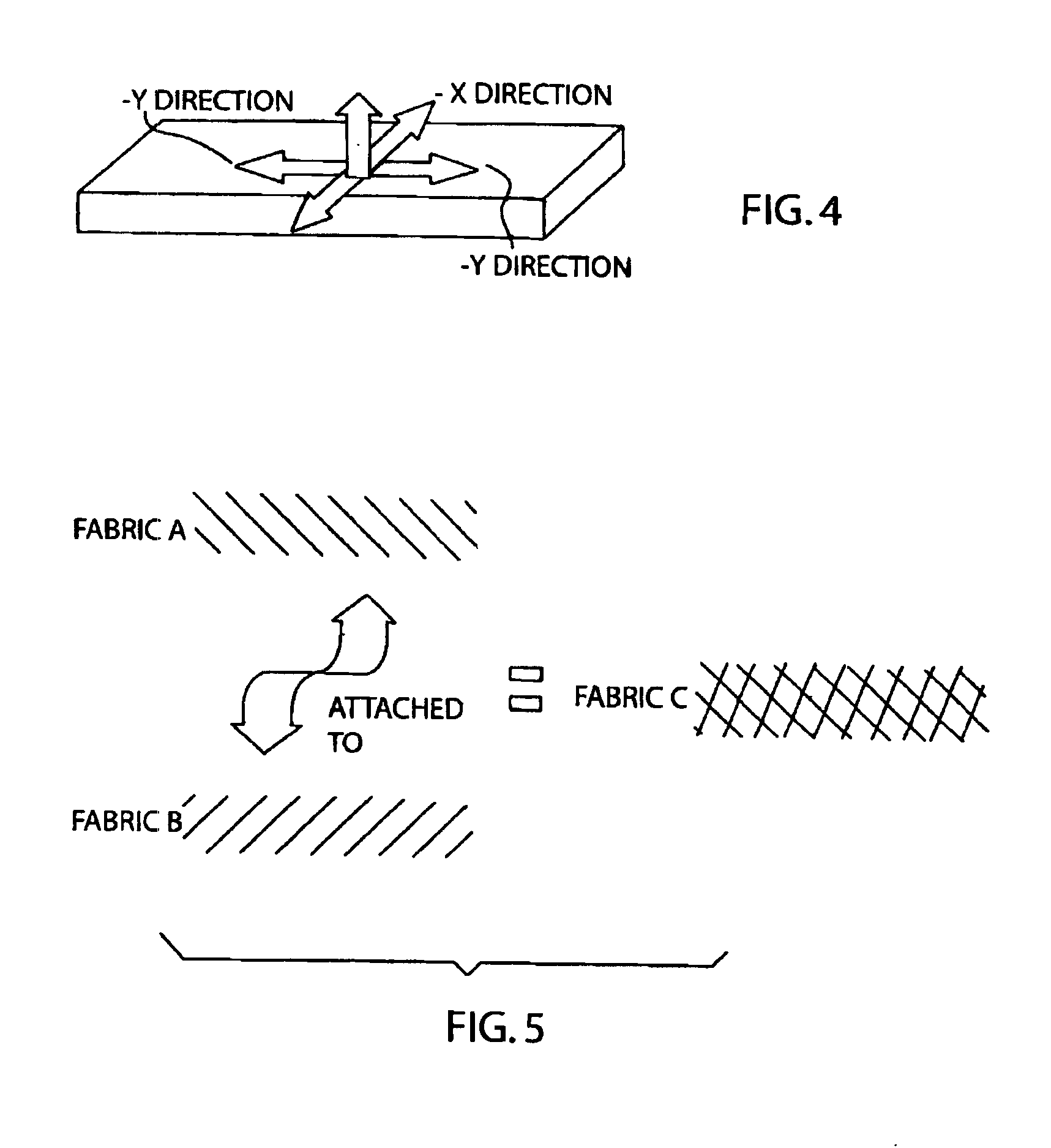
[0037]The cloth was placed between the heel and a Bertec force plate sampling at 120 Hz. The two components of the shear force is separated into an ±X medial to lateral (side to side) and an ±Y anterior posterior (front to back) component with respect to the force collection plate. The positive and negative values only indicate direction of the force with respect to the center of the plate (as seen in FIG. 4).

Example

EXAMPLE II

[0038]Using a TMI (Testing Machines Inc.) Model 32-06 Slip Friction Tester was calibrated and was running in an environment of 72 degrees Fahrenheit at 40% humidity. The following test was performed:

[0039]An 8.5-cm by 33-cm sample of the fiber was fixated to the bed of the test unit. A 6.5-cm by 6.5-cm sample of the fiber was then fixated to the sled of the test unit with the fibers oriented in the same direction as the fibers on the test bed of the unit. This was designated as a 0 (zero) degree orientation. A test for static and dynamic coefficient of friction was then performed according to the ASTM D 1894 protocol. The static measurement is a reflection of the larger frictional forces during the initiation of motion while the kinetic measurement reflects the friction occurring once the sled was already moving. Thirty tests were performed using the same samples for each test.

[0040]The original sample on the sled was then replaced with a sample of the same fiber type with...


PUM

PropertyMeasurementUnit
Angleaaaaaaaaaa
Angleaaaaaaaaaa
Angleaaaaaaaaaa

Abstract

A low friction fabric constructed of a first layer of woven polyester fibers with an upper and lower woven surface attached to and adjacent a second layer of the same weave of polyester fibers, the second layer having an upper and lower surface. Each of the woven layers comprising a straight yarn in the warp of the weave pattern with the weaves of the layers being oriented at a 90 degree angle to one another.

Description

FIELD OF THE INVENTION[0001]This invention relates to a fabric designed to minimize shear forces. It has both medical and recreational applications.BACKGROUND OF THE INVENTION[0002]The formation of calluses is primarily a result of friction. As the layers of skin are loaded in a shearing fashion, the planes of skin separate. This leads to blistering in the space between layers. With further progression of shear loads, the upper layer or layers of skin can be traumatized to the point where it separates from the deeper layers. This results in painful, raw, exposed dermis. In addition to the pain associated with exposure to these deeper layers, there is a danger of progression of the sore as successive layers are forcefully torn away. Ultimately, this can lead to open sores called ulcers. Ulcers occur when the depth of the wound has advanced through the epidermis, dermis, and into the subcutaneous fat layer. This layer is highly vascular, and susceptible to infection.[0003]Separation o...

Claims


Application Information

Patent Timeline
IPC IPC(8): D03D23/00A41B11/00A41B17/00B32B5/26D03D15/00
CPCA41B11/005A41B17/00D03D11/00D03D15/00D03D15/10D10B2509/02D10B2331/04D10B2403/012D10B2501/00D10B2509/00Y10T442/3472Y10T442/3602D03D15/58D03D15/283
Inventor METZGER, MICHAEL B.
Owner DATA TRACE PUBLISHING
Why Eureka
Try Eureka