
Compression apparatus

a compression device and compression tube technology, applied in non-surgical orthopedic devices, physical therapy, massage, etc., can solve the problems of blood accumulation or pooling, life-threatening, and interference with cardiovascular circulation

Active Publication Date: 2007-10-16
KPR U S LLC
View PDF145 Cites 73 Cited by
  • Summary
  • Abstract
  • Description
  • Claims
  • Application Information

AI Technical Summary

Benefits of technology

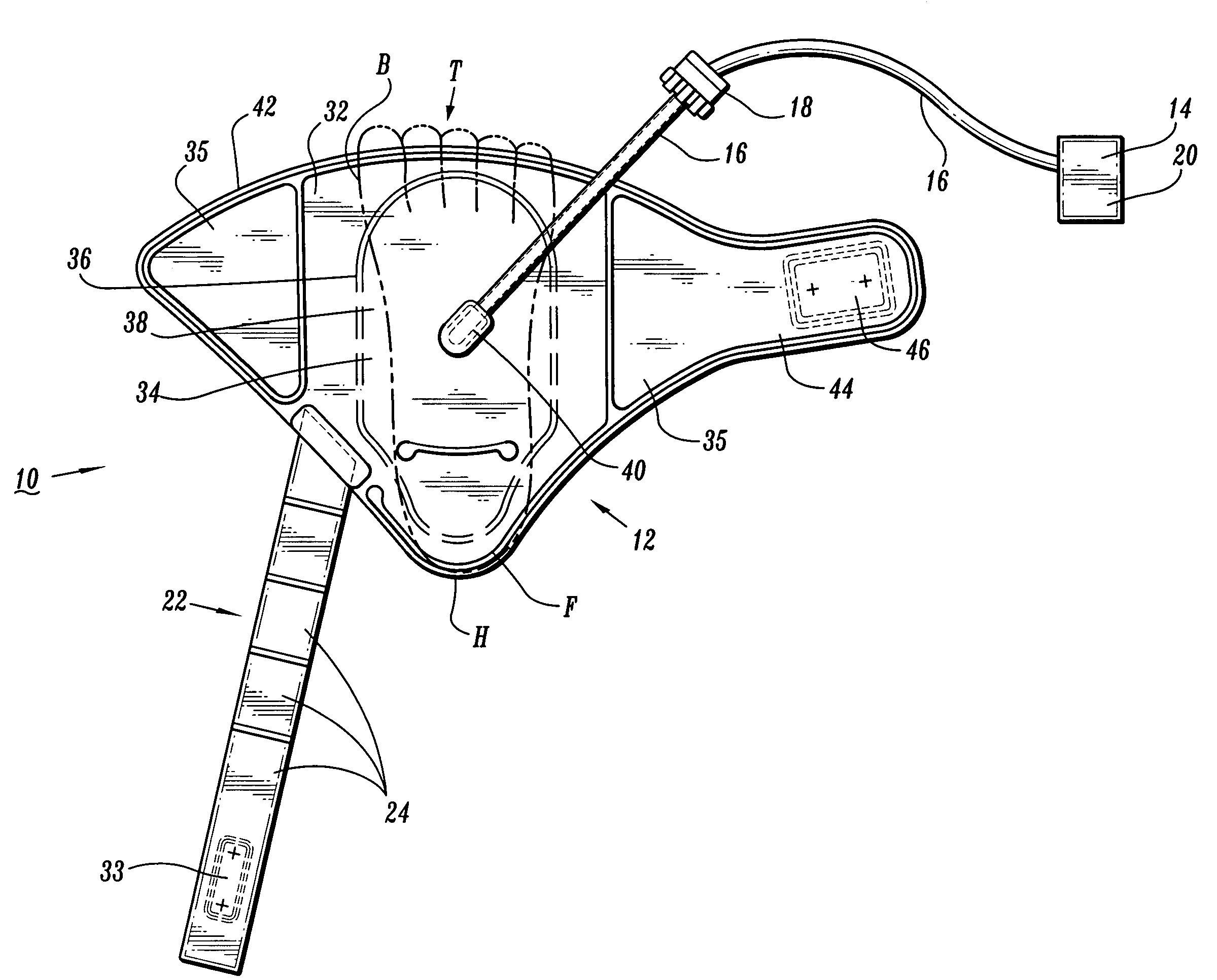
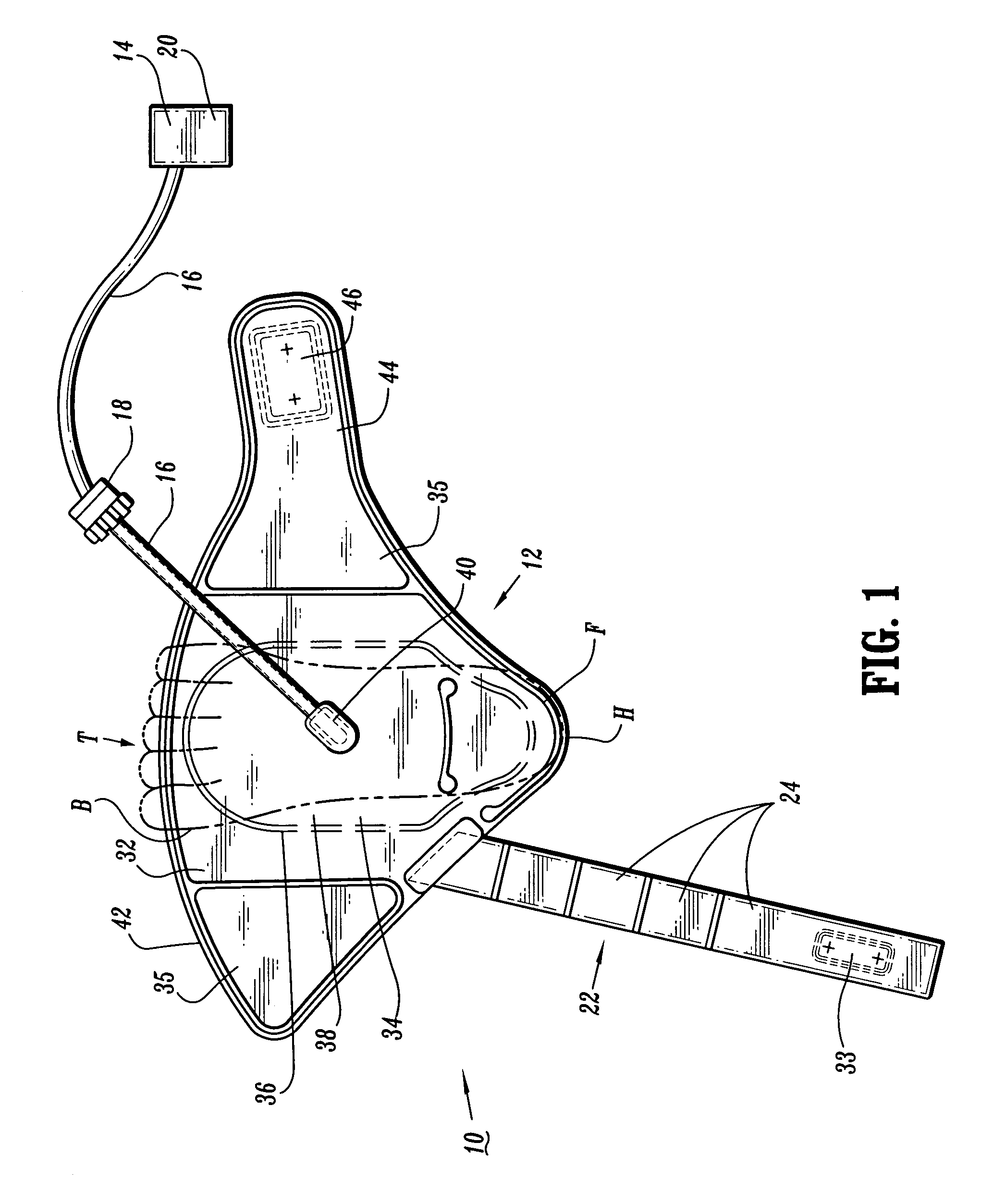
[0009]Accordingly, a compression apparatus is provided that prevents contamination, mitigates the incidence of skin breakdown and facilitates disposal with an extremity for overcoming the disadvantages and drawbacks of the prior art. Desirably, a compression apparatus including the foot sleeve reduces bulk and is not cumbersome during use to improve comfort and compliance to a patient. The compression apparatus is easily and efficiently fabricated.
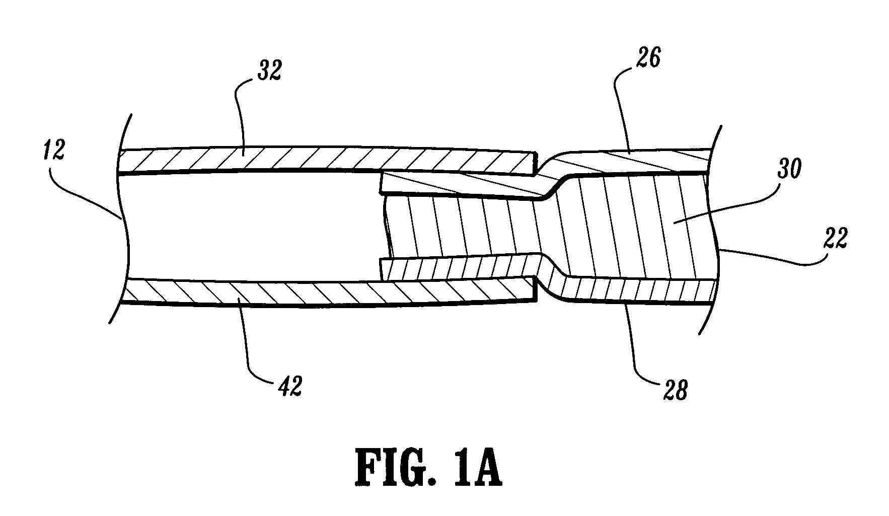
[0013]The compression apparatus includes a strap that improves comfort by using a single piece laminate structure whose inside layer is a cushioning layer. The strap is integrated with a foot sleeve by sandwiching the strap between separate layers of the foot sleeve body. The comfort to the patient may be improved by segmenting the strap to contour about the heel of the foot. The strap can also include one or more layers configured to provide a barrier to the cushioning layer from the environment. The foot sleeve can improve ease of use by having a universal design with a one flap metatarsal closure.
[0014]The strap may include a laminate consisting of various layers. The layers may include a center layer that is configured for comfort. Outside layers disposed about the center layer provide a barrier between the environment and an outer surface of the foot. One of the outside layers can be a skin contact layer that is soft to the touch. The strap may be a separate part integrated into the body of the foot sleeve by being sandwiched between separate layers of the foot sleeve body and then permanently secured. The body of the foot sleeve may be designed for adaptability to various foot sizes and shapes by employing a single metatarsal flap that facilitates ease of use. The body may be configured to provide inspection of the tops of the phalanges of the foot.
[0015]One of the advantages of the present disclosure is a cushioning layer that is not in direct engagement with the outer surface of the foot. The cushioning layer has a soft skin contact layer. The foot sleeve may also include a liner that is configured to provide a physical barrier to the cushioning layer that assists in the prevention of contamination. The interior cushioning layer provides comfort and mitigates skin breakdown. Thus, the foot sleeve improves patient compliance and provides sanitation by isolating the cushioning layer from the environment.
[0016]The foot sleeve is also easily manufactured, for instance, the material stack up contained in the layers allows the strap and / or foot sleeve to be cut as one piece and ensures an even stack up of materials.
[0020]In an alternate embodiment, the compression apparatus has a foot sleeve including an inflatable body configured for disposal about a foot. The foot sleeve includes a metatarsal portion. A strap is integrally connected to the foot sleeve and extends therefrom. The strap is configured for disposal about the foot adjacent an ankle. The strap has a first layer configured to engage an outer surface of the foot adjacent the ankle, a second layer and a third cushion layer is disposed therebetween. The first layer and the second layer are configured to provide a barrier to the third cushion layer. The first layer may be configured to prevent engagement of the third cushion layer with the outer surface of the foot.

Problems solved by technology

For example, when blood circulation in these veins is retarded due to illness, injury or inactivity, there is a tendency for blood to accumulate or pool.
A major risk associated with this condition is interference with cardiovascular circulation.
A pulmonary emboli can form blocking a main pulmonary artery, which may be life threatening.
These known devices may suffer from various drawbacks due to their bulk, cumbersome nature of use, potential for contamination and irritation to the extremity during application and use.
These drawbacks reduce comfort, compliance, cause skin breakdown and may disadvantageously prevent mobility of the patient as recovery progresses after surgery.

Method used


Image

  • Compression apparatus
  • Compression apparatus
  • Compression apparatus

Examples


Embodiment Construction

[0030]The exemplary embodiments of the compression apparatus including the foot sleeve and methods of operation disclosed are discussed in terms of vascular therapy including a compression apparatus for application to a foot or other limb of a body and more particularly in terms of a compression apparatus configured to artificially stimulate the blood vessels of the limb including the foot, heel and toes of a patient. It is contemplated that the compression apparatus may be employed for preventing and overcoming the risks associated with patient immobility. It is further contemplated that the compression apparatus alleviates the conditions arising from patient immobility to prevent for example, DVT, and peripheral edema. It is contemplated that the compression apparatus according to the present disclosure may be employed with various types of venous compression systems, including, but not limited to rapid inflation, slow compression, non-sequential and sequential compression apparat...


PUM


Abstract

A compression apparatus including an expandable body configured for disposal about a foot. A strap extends from the body. The strap is configured for disposal about the foot adjacent an ankle. The strap has a first layer configured to engage an outer surface of the foot adjacent the ankle, a second layer and a third cushion layer disposed therebetween. The body may include a metatarsal portion. The first layer and the second layer may be configured to provide a barrier to the third cushion layer. The first layer may be configured to prevent engagement of the third cushion layer with the outer surface of the foot.

Description

BACKGROUND[0001]1. Technical Field[0002]The present disclosure generally relates to the field of vascular therapy for application to a limb of a body, and more particularly, to a compression apparatus configured to artificially stimulate blood vessels of the limb.[0003]2. Description of the Related Art[0004]A major concern for immobile patients and persons alike are medical conditions that form clots in the blood, such as, deep vein thrombosis (DVT) and peripheral edema. Such patients and persons include those undergoing surgery, anesthesia and extended periods of bed rest. These blood clotting conditions generally occur in the deep veins of the lower extremities and / or pelvis. These veins, such as the iliac, femoral, popiteal and tibial return deoxygenated to the heart. For example, when blood circulation in these veins is retarded due to illness, injury or inactivity, there is a tendency for blood to accumulate or pool. A static pool of blood is ideal for clot formations. A major ...

Claims


Application Information

Patent Timeline
Patent Type & Authority Patents(United States)
IPC IPC(8): A61H9/00A61H7/00A61H23/04
CPCA61H9/0078A61F13/06A61H2201/165A61H2201/1697A61H2209/00A61H2205/12
Inventor GILLIS, HEATHERWATSON, KRISTIN
Owner KPR U S LLC
Learn More