High-frequency heating apparatus

a heating apparatus and high-frequency technology, applied in the direction of electric/magnetic/electromagnetic heating, process and machine control, instruments, etc., can solve the problems of unwanted loss and unwanted noise, and achieve the effect of hardly producing heat loss, hardly generating noise, and not consuming useless energy

Active Publication Date: 2007-10-16
PANASONIC CORP
View PDF7 Cites 17 Cited by
  • Summary
  • Abstract
  • Description
  • Claims
  • Application Information

AI Technical Summary

Benefits of technology

[0066]Since the above-described arrangement is employed, such an inverter circuit can be obtained in which a heat loss can be hardly produced in an IGBT, and thus, useless energy is not consumed, and also, noise can be hardly generated.

Problems solved by technology

As a result, if the other semiconductor switching element is turned ON at this time, then an excessively large current having a spike shape may flow through this turned-ON switching element, so that unwanted loss and undesirable noise may be produced.

Method used


Image

  • High-frequency heating apparatus
  • High-frequency heating apparatus
  • High-frequency heating apparatus

Examples


Embodiment Construction

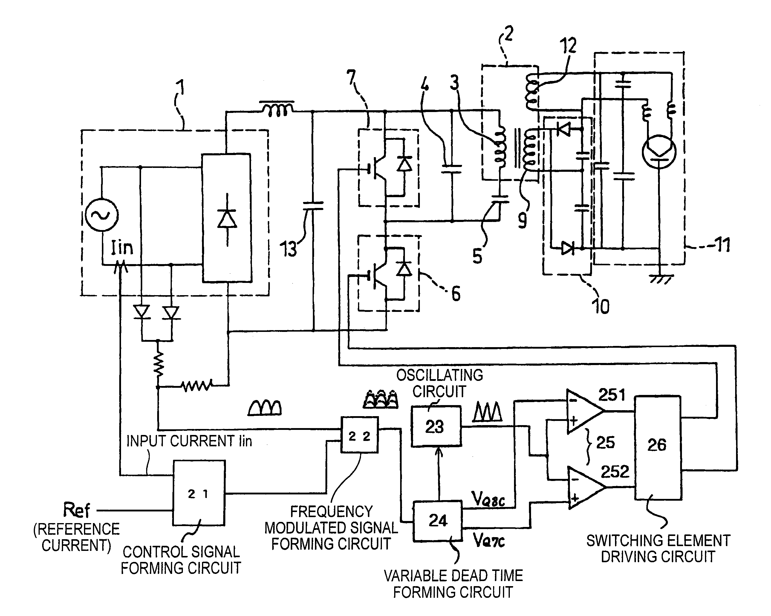
[0106]FIG. 5 is a diagram for showing a high frequency heating apparatus driven by switching elements of a 2-switching element bridge, according to the present invention.

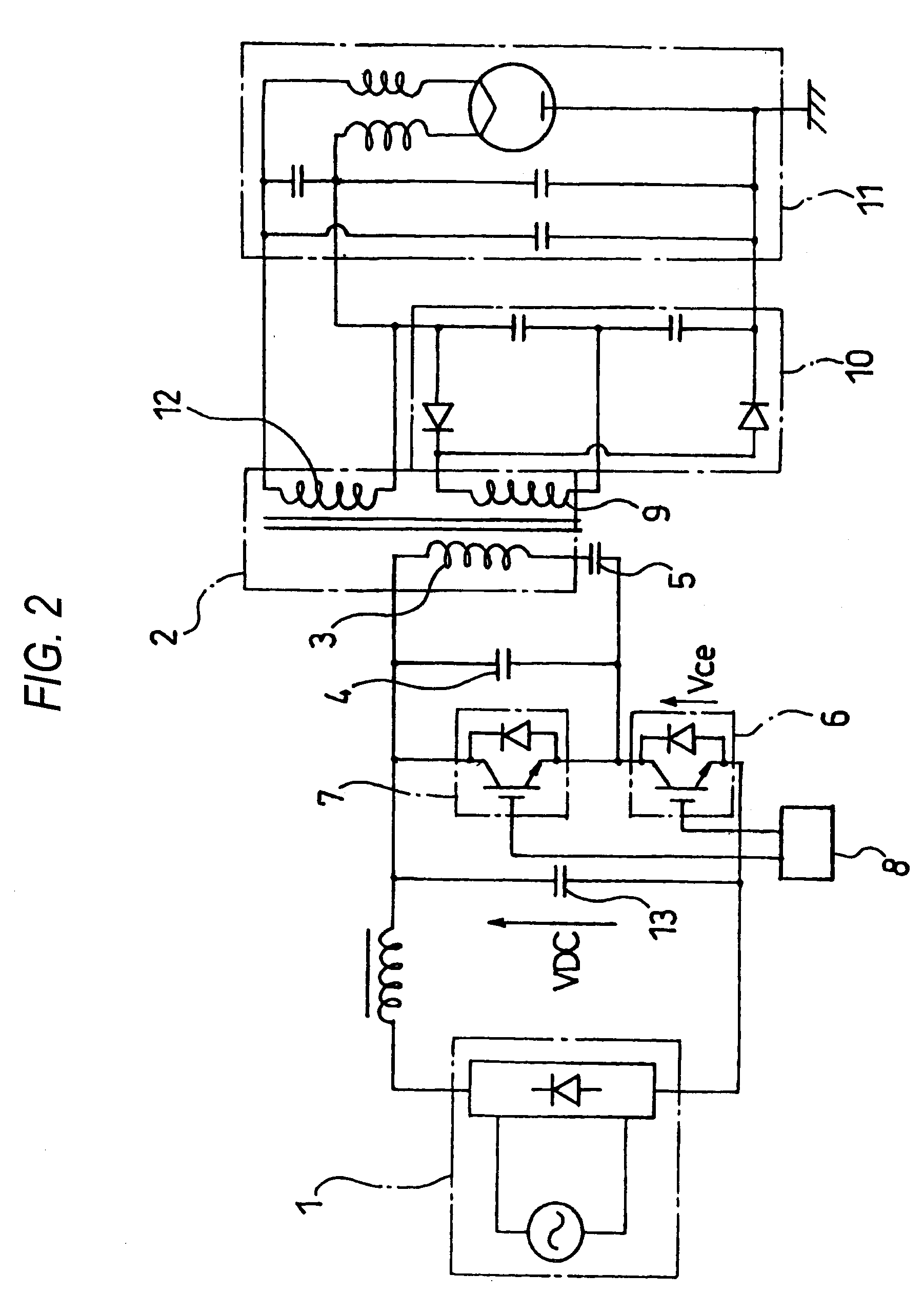
[0107]In this drawing, a major circuit of this high frequency heating apparatus has been arranged by a DC power supply 1, a leakage transformer 2, a first semiconductor switching element 6, a first capacitor 4, a second capacitor 5, a third capacitor (smoothing capacitor) 13, a second semiconductor switching element 7, a driving unit 8, a full-wave doubler rectifying circuit 10, and a magnetron 11. Since the arrangement of the major circuit shown in FIG. 5 is identical to that of FIG. 2, the same explanations are omitted.

[0108]Then, a control circuit for controlling the first and second semiconductor switching elements 6 and 7 is arranged by a control signal forming circuit 21, a frequency modulated signal forming circuit 22, an oscillating circuit 23, a variable dead time forming circuit 24, a rectangular wave form...


PUM


Abstract

A purpose of the present invention is to provide an inverter circuit capable of firmly turning ON IGBTs under limited condition, while a heat loss and noise can be hardly produced in semiconductor switching elements.In a resonant type high frequency heating apparatus which is arranged by employing a DC power supply; a series connection circuit constructed of two semiconductor switching elements which are connected to the DC power supply; another series connection circuit constituted by a capacitor and a primary winding of a leakage transformer connected to both the terminals of one of the two semiconductor switching elements; and a driving means for driving the respective semiconductor switching elements respectively, a variable dead time forming circuit is provided in the driving means, while the variable dead time forming circuit makes a dead time constant at a switching frequency lower than, or equal to a predetermined switching frequency, and also, rapidly increases a dead time at a switching frequency higher than, or equal to the predetermined switching frequency. Furthermore, when the switching frequency becomes high, a limitation is provided by which the dead time is not further widened.

Description

TECHNICAL FIELD[0001]The present invention relates to a high frequency heating apparatus using a magnetron such as a microwave oven. More specifically, the present invention is directed to an inverter circuit of such a high frequency heating apparatus.BACKGROUND ART[0002]Since conventional power supplies mounted on high frequency heating apparatus have been made heavy and bulky, these conventional power supplies are desired to be made compact and light weight. As a result, various technical ideas capable of manufacturing these power supplies in compact, light weight and low cost have be actively progressed in such a way that these power supplies are constructed in switching modes. In high frequency heating apparatus which cook food products by using microwaves generated by magnetrons, various needs capable of making power supplies compact and in light weight have been requested, which are employed so as to drive magnetrons. These needs could be realized by switching-type inverter ci...

Claims


Application Information

Patent Timeline
Patent Type & Authority Patents(United States)
IPC IPC(8): H05B6/68H02M3/337H05B6/04H05B6/66
CPCH05B6/666
Inventor SUENAGA, HARUOMORIYA, HIDEAKISAKAI, SHINICHIMORIKAWA, HISASHISHIROKAWA, NOBUOKINOSHITA, MANABU
Owner PANASONIC CORP
Why Eureka
Try Eureka