Grate structure for solid fuel burners

a solid fuel burner and grate technology, applied in the direction of combustible gas production, combustion process, gasification process details, etc., can solve the problem of difficulty in achieving thorough mixing of fuel and air/gas streams, and achieve the effect of enhancing combustion, steadily and slowly stroke or conveying

Inactive Publication Date: 2007-10-23
SALINAS ENERGY
View PDF12 Cites 2 Cited by
  • Summary
  • Abstract
  • Description
  • Claims
  • Application Information

AI Technical Summary

Benefits of technology

[0024]Preferably, the gasifier has a solid fuel inlet positioned generally behind the grate structure(s) relative to a general direction of projection of the grate structure and overall direction of flow of the fuel, whereby in use of the gasifier a deep burden of fuel accumulates on the g

Problems solved by technology

Problems experienced with gasifiers, as with many other high temperature furnace processes, include sinterin

Method used


Image

  • Grate structure for solid fuel burners
  • Grate structure for solid fuel burners
  • Grate structure for solid fuel burners

Examples


Embodiment Construction

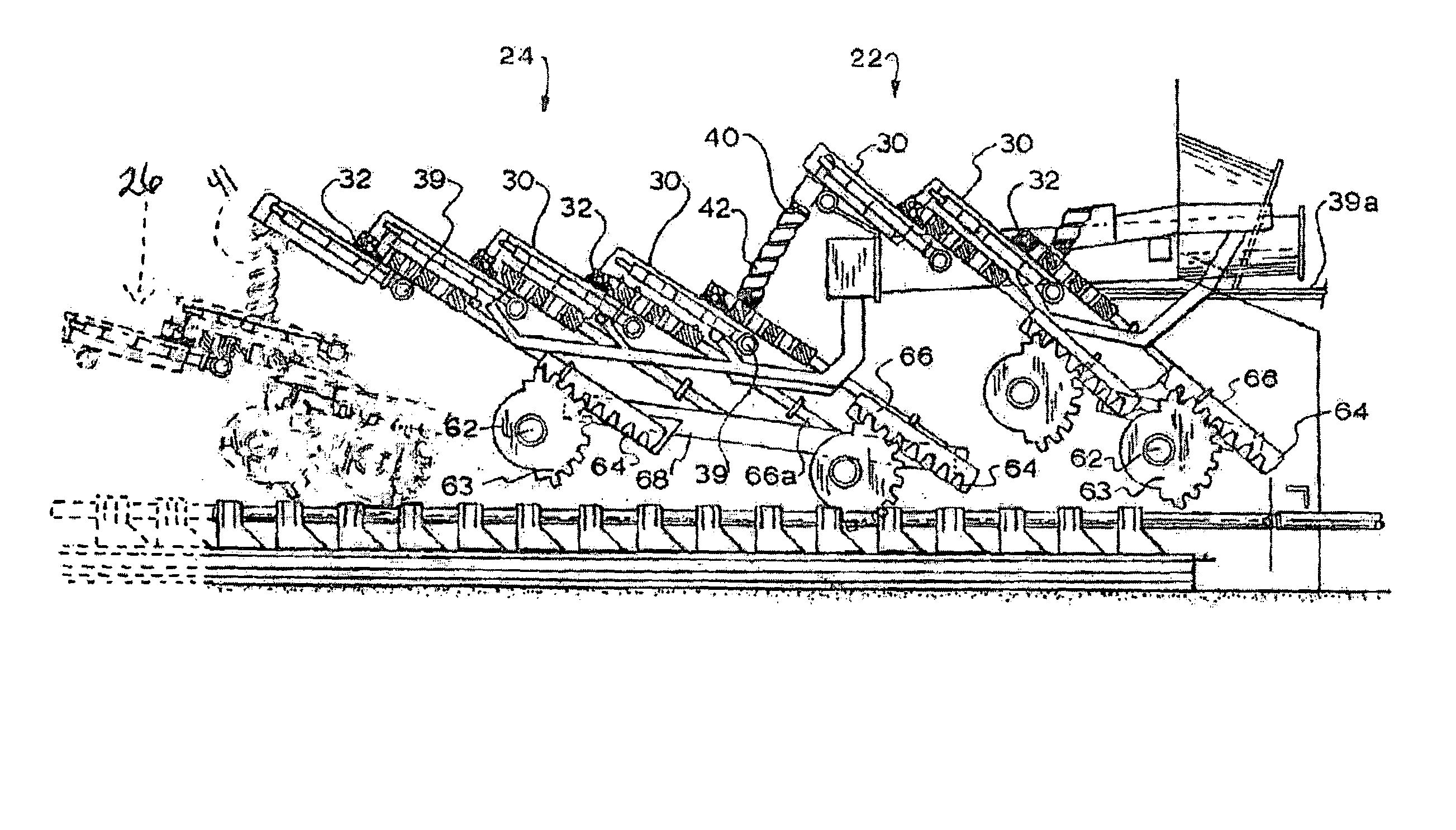
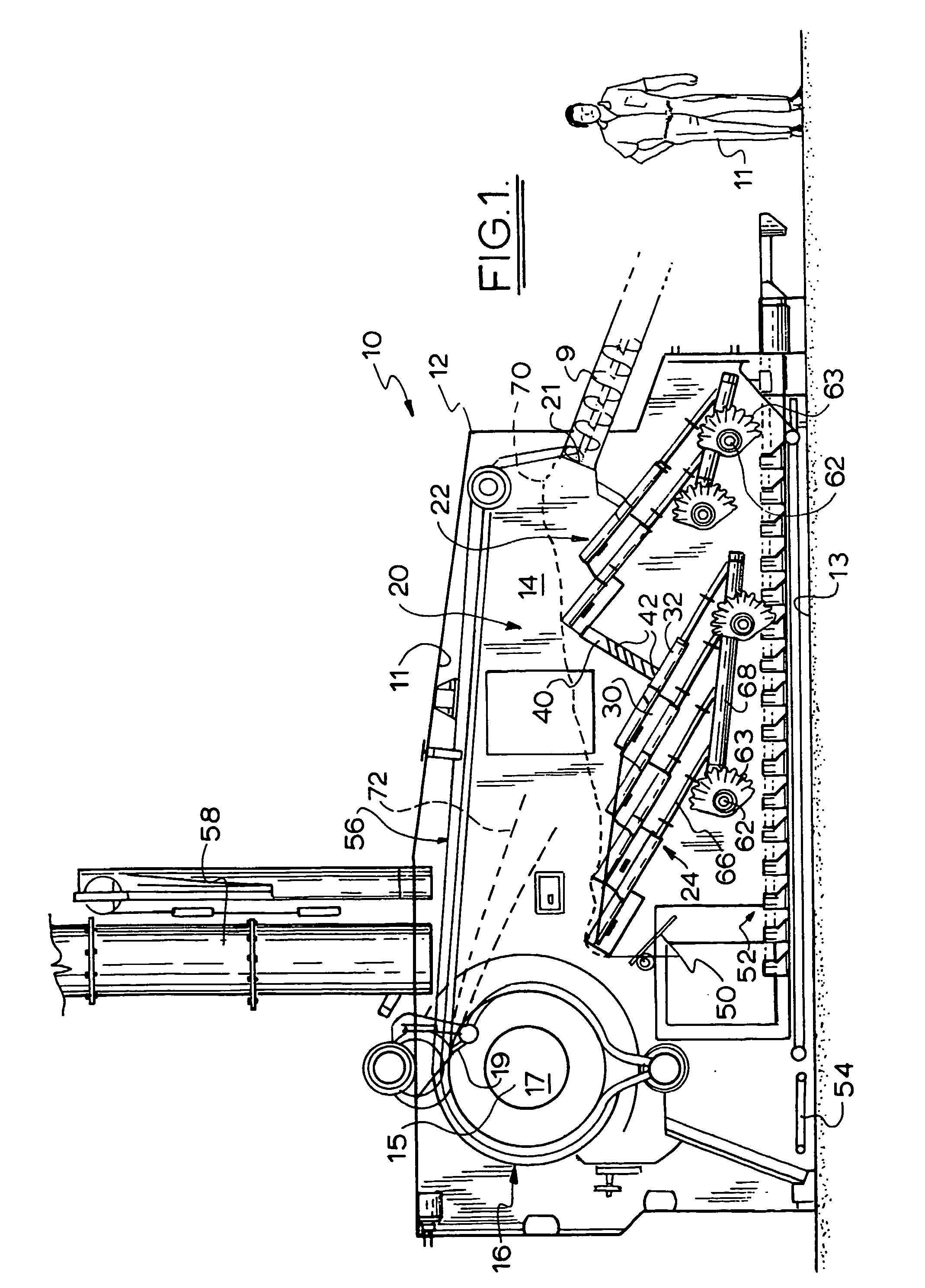
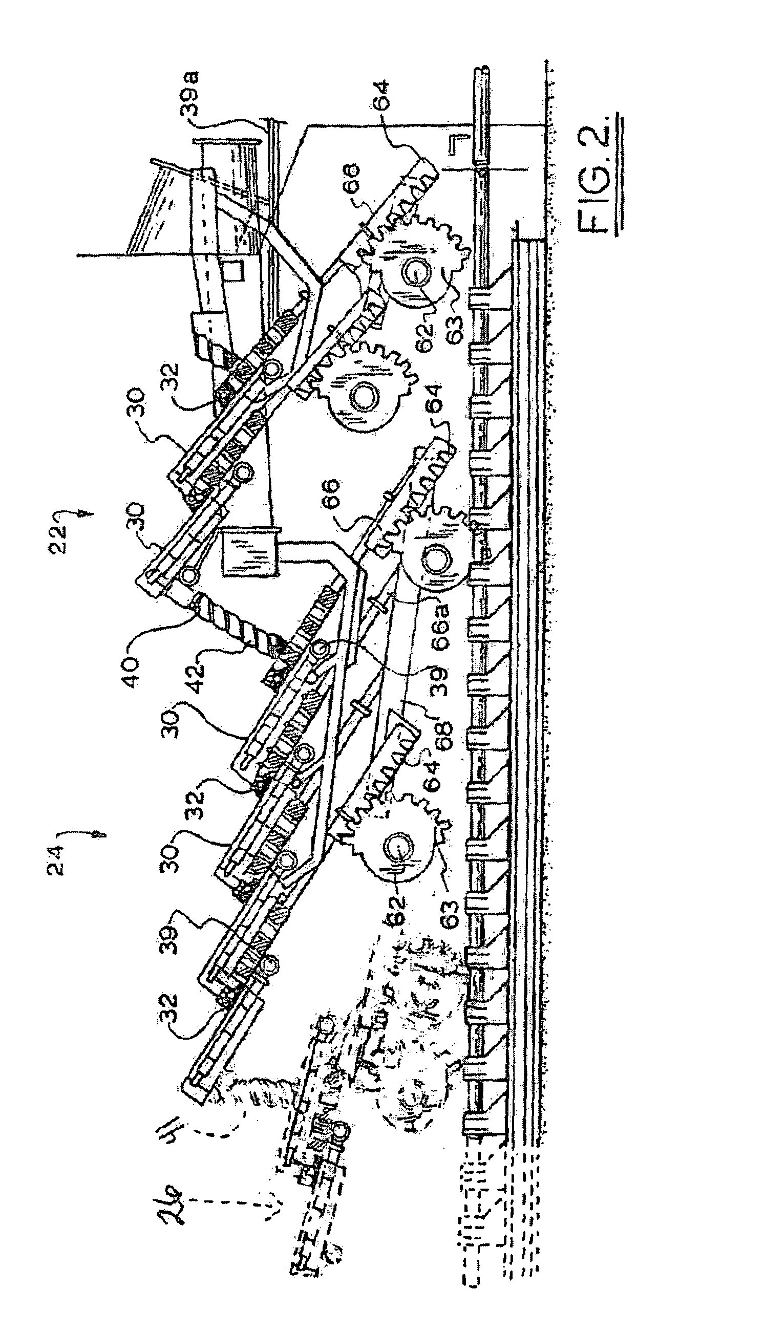
[0036]The solid fuel gasifier 10 of FIG. 1 (which includes a figure of a man 11 to provide a dimensional context), includes an outer housing 12 about a gasification chamber 14 extending from a fuel delivery auger 9 towards a separately walled cycloburner 16 that defines a secondary combustion chamber 17. A grate structure 20 includes a preheating grate 22 adjacent the delivery end of auger 9, and, downstream in the overall direction of flow of the solid fuel, a gasifier grate 24. The two grates 22, 24 each include stepped pairs of fixed 30 and reciprocating 32 grate segments and are linked by a near vertical grate 40 with multiple angled and controllable openings 42 for admission of combustion air from below the grate structure into the fuel load above. It will be seen that the solid fuel inlet 21 into chamber 14 from auger 9 is generally behind the grate structure 20 relative to the general direction of projection of the grate structure and the overall direction of flow of the soli...


PUM


Abstract

In one aspect, a grate segment for a burner, comprises a substantially rigid body (30) having a dispersed array of cavities (38) filled with a refractory material. In another aspect, a solid fuel gasifier includes a housing (12) defining a gasifier chamber (14), and a solid fuel inlet (21), grate structure (22, 24) in the gasifier chamber. The grate structure includes base means, a plurality of agitator segments (32) positioned relative to the base means for reciprocating movement to agitate a fuel load in the gasifier, and means to support the base means and the agitator segments so that the latter reciprocate in a direction at a substantial inclination to both horizontal and vertical. In use of the gasifier a deep burden of fuel accumulates on the grate structure and the outward stroke of the reciprocation of the agitator elements is in the overall direction of flow of the fuel burden or generally oppositely thereto.

Description

CROSS-REFERENCE TO RELATED APPLICATIONS[0001]This application is a U.S. National Stage of International Application No. PCT / AU01 / 01666 filed 21 Dec. 2001. This application claims the benefit of Australian Application No. PR 2291, filed 22 Dec. 2000. The disclosure(s) of the above applications are incorporated herein by reference.FIELD OF THE INVENTION[0002]This invention relates generally to solid fuel burners and has particular, though not exclusive, application to a solid fuel burner of the type commonly referred to as a gasifier or gasifier combustor.BACKGROUND ART[0003]A gasifier generally includes a primary combustion chamber into which solid fuel is loaded on to a grate structure on which it is first dried and gasified via controlled primary combustion. The resultant gas is then transferred into a secondary combustion chamber, which may conveniently be a cycloburner, for secondary combustion to produce a high temperature relatively clean flue gas able to be used for a variety ...

Claims


Application Information

Patent Timeline
IPC IPC(8): F23H7/08C10J3/72F23H1/02F23H17/12
CPCC10J3/72F23H1/02F23H7/08F23H17/12C10J3/002C10J2200/158F23H2900/17001C10J2300/1223C10J2300/1625F23H2900/03021Y02P20/133
Inventor WILLIAMS, PAUL DOUGLASWILLIAMS, GERALD DAVID
Owner SALINAS ENERGY
Why Eureka
Try Eureka