Can extractor apparatus

a technology of extractor and cannon, which is applied in the direction of conveyor parts, transportation and packaging, disinfection, etc., can solve the problems of corrosive environment, excessive wear, and heavy use, and achieve the effects of reducing the scratching of cans, reducing the transfer of rust, and increasing the life of the extractor

Active Publication Date: 2007-10-23
ALLIED MACHINE
View PDF13 Cites 5 Cited by
  • Summary
  • Abstract
  • Description
  • Claims
  • Application Information

AI Technical Summary

Benefits of technology

[0017]One embodiment of the invention is a can extractor having a stainless steel clover wheel, a star wheel and hub flanges or plates that come in contact with the cans from the cookers / coolers. Stainless steel contact components completely eliminate the transfer of rust to the cans. The stainless steel components of the present invention also reduces scratching of cans because the liquid from the cooker / cooler on the stainless steel contact surfaces acts as a lubricant between the extractor component and the rotating can.
[0018]A new center bearing design is used which markedly increases the life of the extractor and minimizes sleeve damage due to a jam. In one embodiment, needle bearings are positioned to support the rotating sleeve on the center shaft with ports through the center shaft for lubrication. In another embodiment, a plastic bushing with internal lubrication are used to support the sleeve on the shaft. A bushing or bearing is used to support the stationary discharge chute on the rotating sleeve. A keyless shaft / hub locking device is used on the star wheel hub instead of set screws or keyways to align the star wheel with the clover wheel (timing lock) to provide uniform compressive force on the sleeve and limited slipping to minimize damage to the rotating sleeve if a jam occurs.
[0019]Another embodiment of the invention is a can extractor with a plastic clover wheel and plastic star wheel back plate that is configured to eliminate rust on contact surfaces, but with the added benefit of an “easy-touch” surface which eliminates most, if not all, scratching on the cans caused by contact with the extractor. With the elimination of scratching, the food processor is able to switch to tin-free steel (TFS) cans at a great cost savings. For example, during a normal 70 day run (an average canning season) a processor may run 200,000 cases per day, 6 cans per case, or 1,200,000 cans per day. A TFS can costs one cent ($0.01) less than a regular can. Thus, the processor would realize a savings of about $840,000 using the can extractor with plastic contact surfaces of the present invention during a regular canning season.

Problems solved by technology

The extractors on these cookers are in continuous use during the canning season and subject to heavy use, excessive wear and are exposed to a wet, corrosive environment associated with food cookers.
As a result, rust forms on the mild steel components at wear and contact surfaces.
The rusty surfaces of the extractor transfer rust to the exterior of the cans during extraction causing damage, discoloration and potential contamination to the product resulting in rejection of product and revenue loss.
It is not uncommon for food processors to replace most or all of the mild steel components of an extractor after each canning cycle due to wear and corrosion.
Another source of product loss associated with existing can extractors is scratching cans while in the extractor.
Wear and corrosion on the mild steel star wheels and flanges develop into sharp edges and rough surfaces.
A scratched can is typically rejected because it is cosmetically unmarketable or the location of the scratch can potentially contaminate the product.
A further source of product loss is a can jammed in an extractor.
Jams can result from failed parts, defective or bulging cans or misalignment of parts due to vibration or wear.
If the jam is not quickly resolved, all the product remaining in the cooker can be ruined.
If repetitive extractor jams cause significant delays in food processing, harvested food product can perish before it is canned and cooked.
These couplings are not designed to give or slip.
When a jam occurs, the torque transmitted through the keyways or set screws of the hubs can damage or distort the soft metal sleeve requiring immediate disassembly and replacement.
Torque from a jam can also damage hubs or shafts requiring costly downtime and replacement.

Method used


Image

  • Can extractor apparatus
  • Can extractor apparatus
  • Can extractor apparatus

Examples


Embodiment Construction

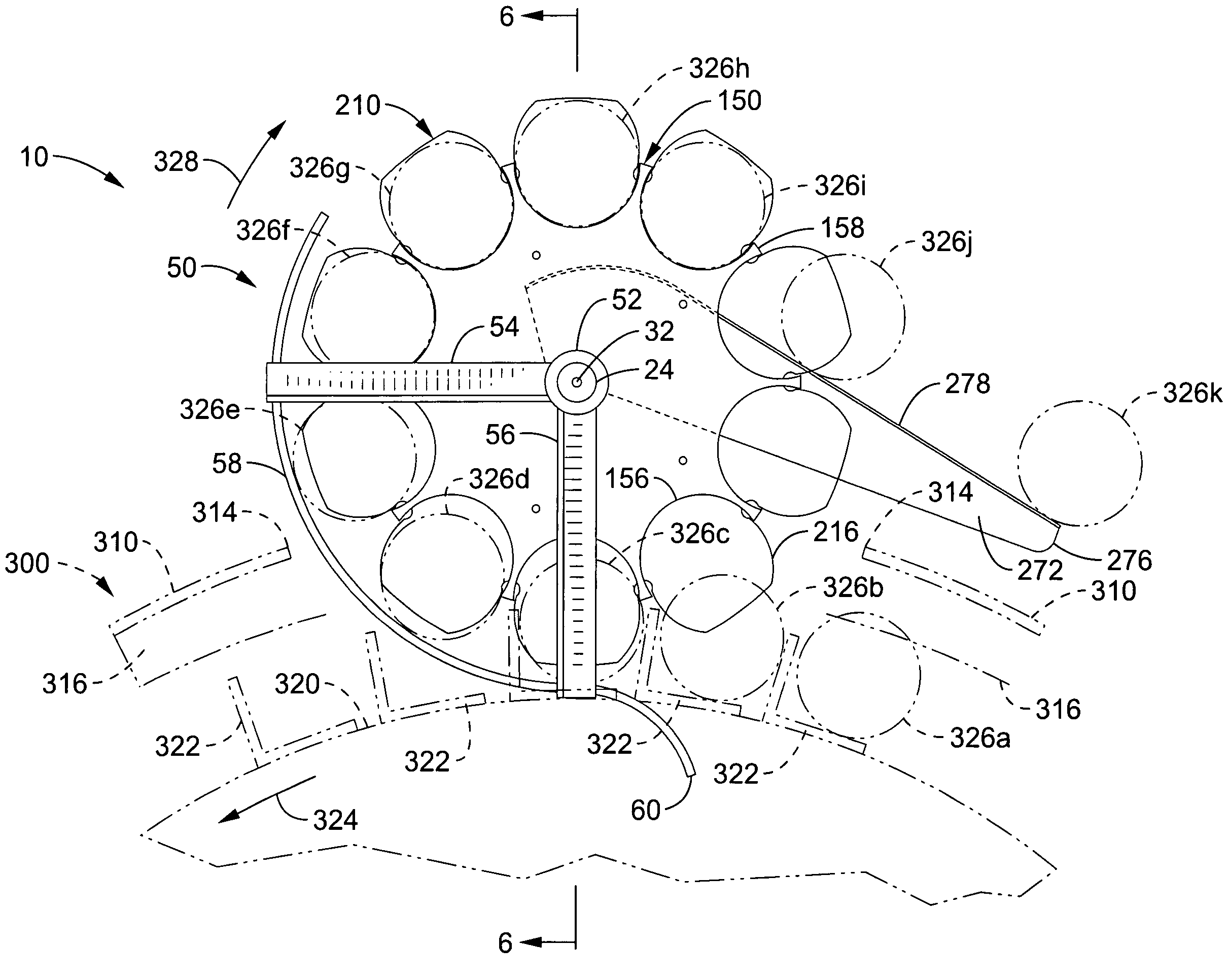
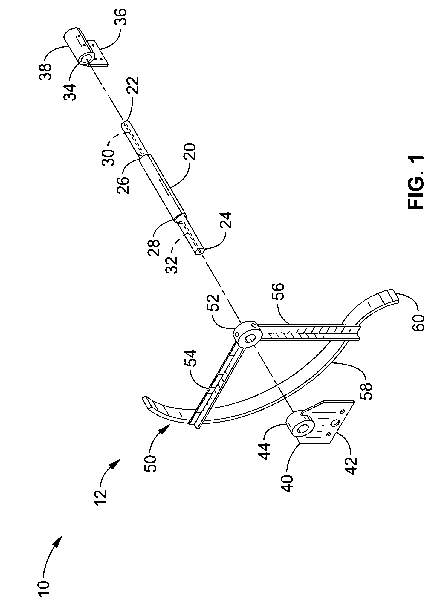
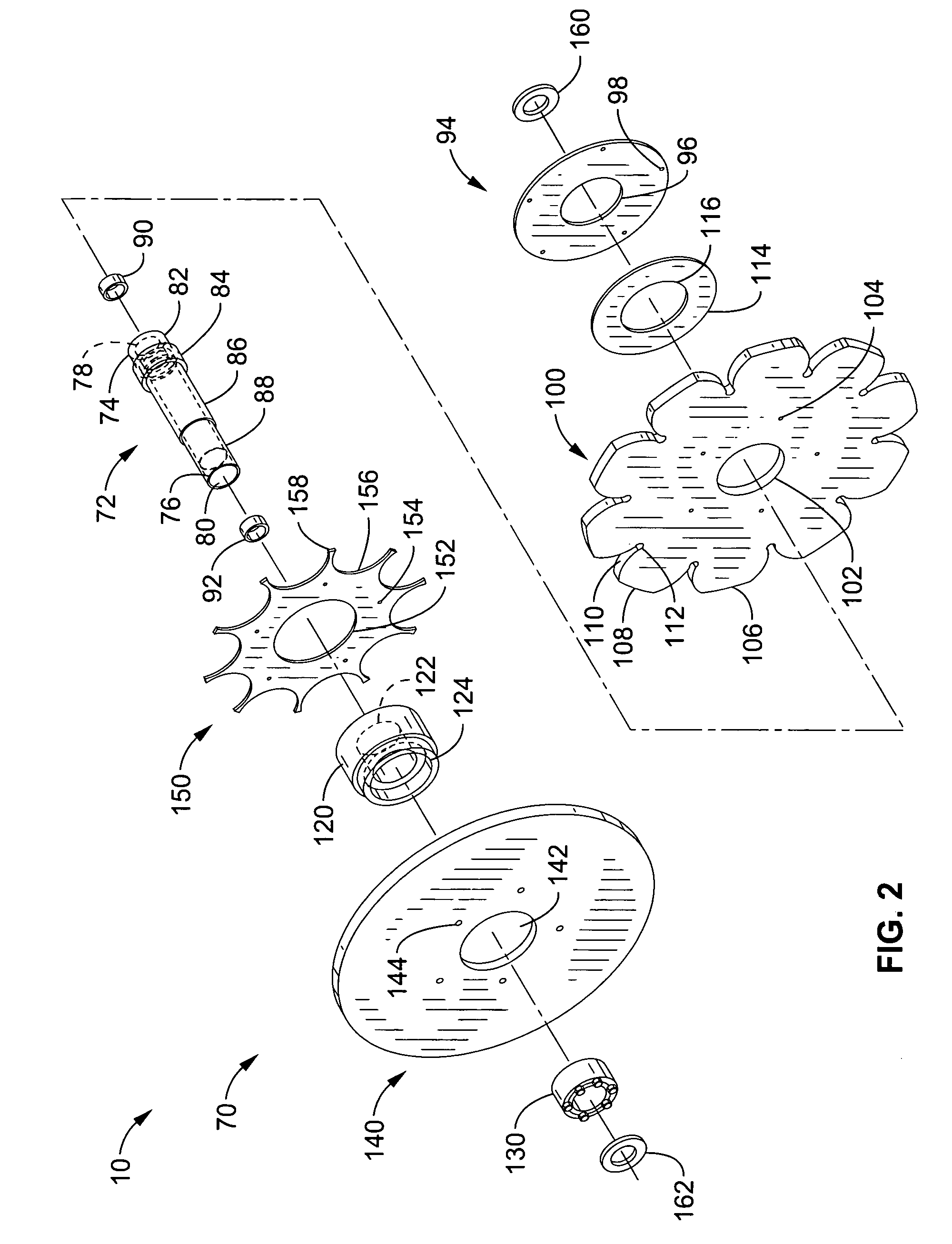
[0050]Referring more specifically to the drawings, for illustrative purposes the present invention is embodied in the apparatus generally shown in FIG. 1 through FIG. 9. It will be appreciated that the apparatus may vary as to configuration and as to details of the parts, and that the method may vary as to the specific steps and sequence, without departing from the basic concepts as disclosed herein.

[0051]FIG. 1 through FIG. 4 are exploded views of the components of a can extractor according to the present invention and generally designated as 10. In order to better understand the relationship of the can extractor components, FIG. 1 illustrates a first sub-assembly consisting of a central shaft and stationary components coupled to the shaft. FIG. 2 illustrates a second sub-assembly comprising a rotating sleeve and stainless steel can handling components coupled to the sleeve that rotates on the center shaft shown in FIG. 1. FIG. 3 illustrates another embodiment of a second sub-assem...


PUM


Abstract

A can extractor for atmospheric rotary cookers and coolers has a clover wheel, a star wheel and a star wheel flange made of stainless steel. The clover wheel and star wheel are aligned and coupled to a sleeve rotating on a stationary shaft. The star wheel is coupled to the sleeve using an adjustable keyless hub / shaft locking device. The clover wheel and star wheel are spaced to accommodate bulging or deformed cans. A center discharge chute is supported on the rotating sleeve with a plastic bushing. Cans from the reel of a cooker / cooler are positioned with a can stripper between the star wheel and clover wheel while the reel rotates the clover wheel. The stainless steel components reduce scratching and eliminate transfer of rust to cans. A plastic clover wheel and a plastic star wheel flange are disclosed that do not scratch or transfer rust to the cans.

Description

CROSS-REFERENCE TO RELATED APPLICATIONS[0001]This application claims priority from U.S. provisional application Ser. No. 60 / 570,958 filed on May 12, 2004, incorporated herein by reference in its entirety.STATEMENT REGARDING FEDERALLY SPONSORED RESEARCH OR DEVELOPMENT[0002]Not ApplicableINCORPORATION-BY-REFERENCE OF MATERIAL SUBMITTED ON A COMPACT DISC[0003]Not ApplicableNOTICE OF MATERIAL SUBJECT TO COPYRIGHT PROTECTION[0004]A portion of the material in this patent document is subject to copyright protection under the copyright laws of the United States and of other countries. The owner of the copyright rights has no objection to the facsimile reproduction by anyone of the patent document or the patent disclosure, as it appears in the United States Patent and Trademark Office publicly available file or records, but otherwise reserves all copyright rights whatsoever. The copyright owner does not hereby waive any of its rights to have this patent document maintained in secrecy, includ...

Claims


Application Information

Patent Timeline
Patent Type & Authority Patents(United States)
IPC IPC(8): B65G29/00
CPCA23L3/001B65G29/00B65G2201/0252
Inventor STEJSKAL, JEFFREY E.
Owner ALLIED MACHINE
Why Eureka
Try Eureka