Microresonator, manufacturing method, and electronic apparatus

a manufacturing method and micro-resonator technology, applied in waveguide devices, instruments, projectors, etc., can solve the problems of difficult to ensure a desired frequency characteristic and frequency characteristic deterioration, and achieve the effect of less susceptible to deterioration

Inactive Publication Date: 2007-10-23
SONY CORP
View PDF5 Cites 5 Cited by
  • Summary
  • Abstract
  • Description
  • Claims
  • Application Information

AI Technical Summary

Benefits of technology

[0006]Specifically, the size of formed resonator elements is apt to have variation since high formation accuracy is required for forming the resonator elements. Therefore, a microresonator has a tendency in that there is variation in the central frequency among the resonator elements. In order to suppress the variation in the central frequency, it is conceivable that the length of an essential part (vibration part) of the resonator element is designed to be larger so that the formation accuracy of the resonator element may permit a margin of error, to thereby suppress the variation in the size of the formed resonator elements. However, if the length of the vibration part of the resonator element is larger, the thickness of the vibration part also needs to be larger in order to enhance the central frequency. However, if the thickness of the vibration part is larger than about 1 μm, the influence of mutual interference arising among the resonator elements is large, which easily causes the deterioration of the frequency characteristic. Therefore, in order to ensure a desired frequency characteristic of the microresonator applied to a high-frequency filter, a need arises to establish a technique capable of suppressing the influence of mutual interference arising among the resonator elements. In addition, it is also essential to establish a technique allowing easy manufacturing of the microresonator in consideration of mass-productivity of the microresonators in particular.
[0018]According to the electronic apparatus of the embodiment of the present invention, the frequency characteristic is less susceptible to deterioration due to the influence of mutual interference arising among the resonator elements based on a structural characteristic of including the microresonator having the above-described structural characteristics. Therefore, a desired frequency characteristic can be ensured due to the microresonator.

Problems solved by technology

However, microresonators in related art cannot sufficiently suppress the influence of mutual interference among the resonator elements due to the structural factors thereof, and therefore involve difficulties of ensuring a desired frequency characteristic.
However, if the thickness of the vibration part is larger than about 1 μm, the influence of mutual interference arising among the resonator elements is large, which easily causes the deterioration of the frequency characteristic.

Method used


Image

  • Microresonator, manufacturing method, and electronic apparatus
  • Microresonator, manufacturing method, and electronic apparatus
  • Microresonator, manufacturing method, and electronic apparatus

Examples


first embodiment

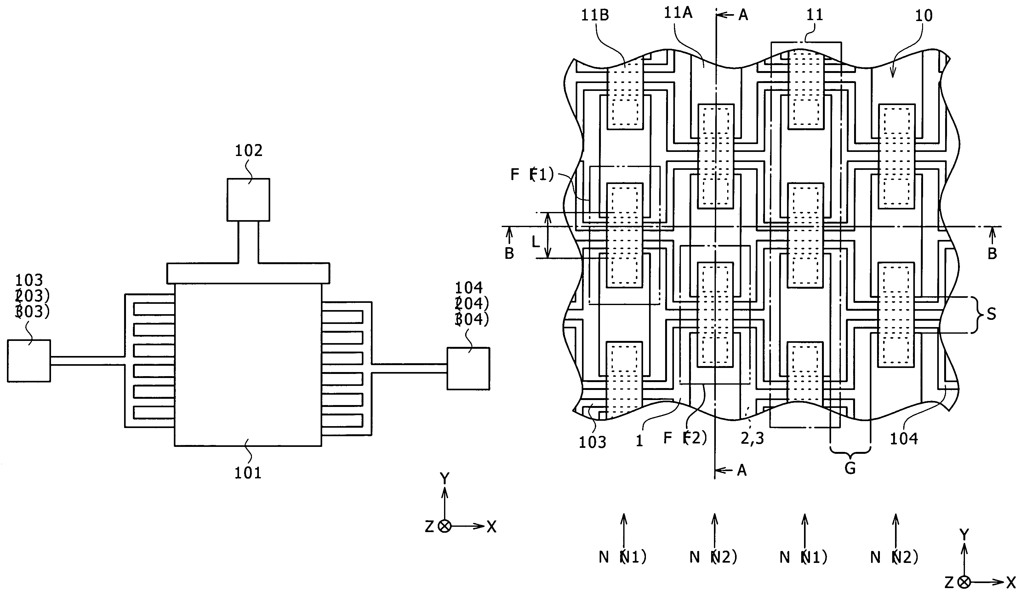
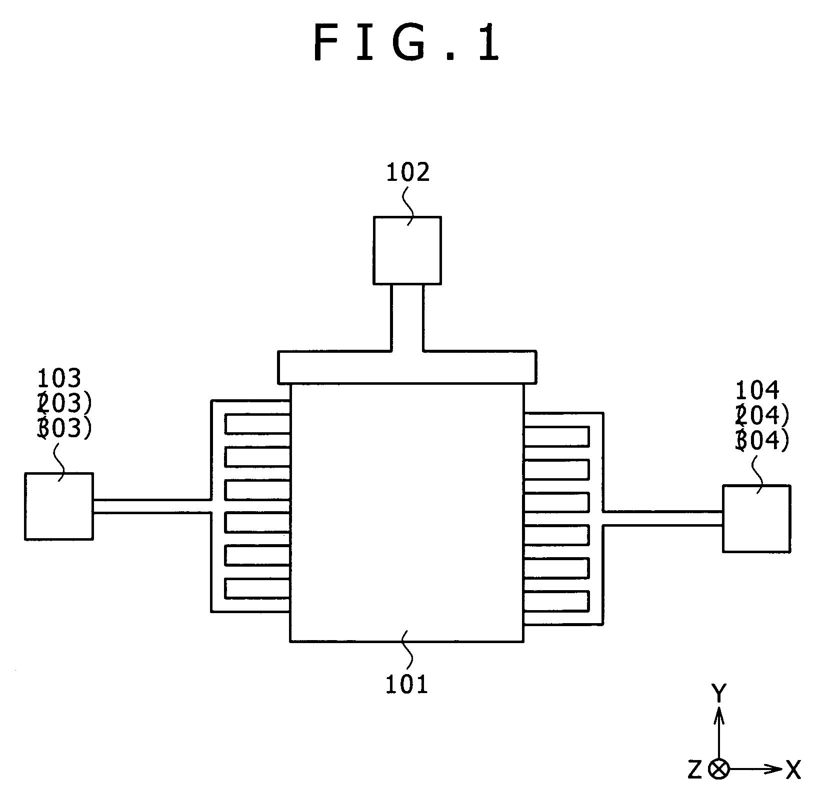
[0054]The structure of a microresonator according to a first embodiment of the invention will be described with reference to FIG. 1. FIG. 1 illustrates the planar structure (planar structure along the XY-plane) of the microresonator.

[0055]The microresonator according to the present embodiment is a microstructure (so-called micromachine) used for controlling frequencies for example. Specifically, the microresonator is applied, as a high-frequency filter having a mechanism for controlling frequencies, to an electronic apparatus typified by a communication device such as a cellular phone used in a wireless communication field. Referring to FIG. 1, the microresonator includes a resonant circuit 101 that is an essential part implementing resonant operation, and three electrodes provided for the resonant circuit 101: a DC applying electrode 102 for applying direct current voltages; an input electrode 103 for inputting signals; and an output electrode 104 for outputting signals. Both the i...

second embodiment

[0085]A second embodiment according to the invention will be described below.

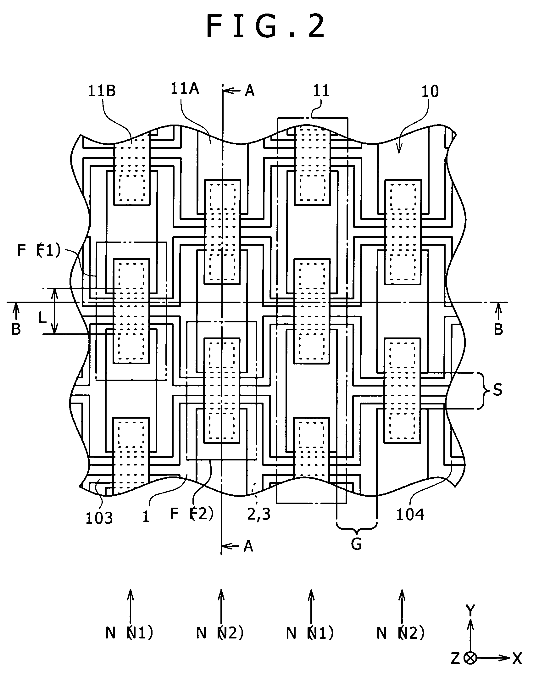
[0086]Initially, the structure of a microresonator according to a second embodiment of the invention will be described with reference to FIGS. 15 to 17. FIGS. 15 to 17 illustrate the structure of the resonant circuit 101 shown in FIG. 1 in a magnified form. FIG. 15 illustrates the planar structure (planar structure along the XY-plane). FIG. 16 illustrates the sectional structure along the line A-A of FIG. 15 (sectional structure along the YZ-plane). FIG. 17 illustrates the sectional structure along the line B-B of FIG. 15 (sectional structure along the XZ-plane).

[0087]The microresonator according to the present embodiment has almost the same structure as that of the microresonator of the first embodiment (refer to FIGS. 1 to 4), except that the present embodiment includes a microresonator structure 20 instead of the microresonator structure 10, and the microresonator structure 20 includes an input electrode...

third embodiment

[0102]A third embodiment according to the invention will be described below.

[0103]Initially, the structure of a microresonator according to a third embodiment of the invention will be described with reference to FIGS. 24 to 26. FIGS. 24 to 26 illustrate the structure of the resonant circuit 101 shown in FIG. 1 in a magnified form. FIG. 24 illustrates the planar structure (planar structure along the XY-plane). FIG. 25 illustrates the sectional structure along the line A-A of FIG. 24 (sectional structure along the XZ-plane). FIG. 26 illustrates the sectional structure along the line B-B of FIG. 24 (sectional structure along the YZ-plane).

[0104]The microresonator according to the present embodiment has almost the same structure as that of the microresonator of the first embodiment (refer to FIGS. 1 to 4), except that the present embodiment includes a microresonator structure 30 instead of the microresonator structure 10, and the microresonator structure 30 includes an input electrode 3...


PUM


Abstract

The present invention provides a microresonator including a plurality of resonator elements arranged on a plurality of columns on a substrate. The resonator elements each have an input electrode, an output electrode, and a diaphragm that extends in a certain direction, and each pass a signal of a certain frequency. The plurality of resonator elements includes a plurality of first resonator elements arranged on first columns that are located on every other column of the plurality of columns, and having a first phase, and a plurality of second resonator elements arranged on second columns that are located on every other column, other than the first columns, of the plurality of columns, and having a second phase that is an opposite phase of the first phase.

Description

CROSS REFERENCES TO RELATED APPLICATIONS[0001]The present invention contains subject matter related to Japanese Patent Application JP 2004-294891 filed in the Japanese Patent Office on Oct. 7, 2004, the entire contents of which being incorporated herein by reference.BACKGROUND OF THE INVENTION[0002]The present invention relates to a microresonator applied to a high-frequency filter for example, a manufacturing method thereof, and an electronic apparatus including a microresonator, typified by a communication device such as a cellular phone.[0003]In recent years, micro resonator elements formed by using semiconductor processes have been known. An example of the resonator elements is disclosed in “High-QVHF micromechanical contour-mode disk resonators”, J. R. Clark, W. -T. Hsu, and C. T. -C. Nguyen, Technical Digest, IEEE Int. Electron Devices Meeting, San Francisco, Calif., Dec. 11-13, 2000, pp. 399-402, for example. The resonator elements have three features: small occupation area, ...

Claims


Application Information

Patent Timeline
Patent Type & Authority Patents(United States)
IPC IPC(8): H03H9/24H03H3/007H03H9/46
CPCH03H9/02259H03H9/02433H03H9/2463H03H3/0072H03H9/525H03H9/462H03H2009/02511G03B21/16H01P11/00
Inventor TADA, MASAHIROTANAKA, MASAHIROMITARAI, SHUNNANIWADA, KOJI
Owner SONY CORP
Why Eureka
Try Eureka