Variable focal length lens system and imaging apparatus

a variable focal length and lens technology, applied in the field of new variable focal length lens system and imaging apparatus, can solve the problems of weakening refractive power, easy compromise of performance, and compromising performance, and achieve the effect of high zoom ratio and miniaturization

Inactive Publication Date: 2007-10-23
SONY CORP
View PDF4 Cites 37 Cited by
  • Summary
  • Abstract
  • Description
  • Claims
  • Application Information

AI Technical Summary

Benefits of technology

[0020]According to the present invention, a high zoom ratio and miniaturization may be achieved.

Problems solved by technology

However, there is an issue with the above-mentioned zoom lenses of related art in that, since the zooming function centers on the second lens group, performance is compromised if the second lens group is misaligned even by the smallest amount at the time of manufacture.
Since the positive spherical aberration that occurs at the second lens group is corrected by the image-side lens surface of a second negative lens of the second lens group and the object-side lens surface of a positive lens located on the image-side of the above-mentioned negative lens, performance is easily compromised if the above-mentioned two lens surfaces are misaligned.
As a result, it is possible to weaken the refractive power of the image-side lens surface of the second negative lens, thereby reducing performance degradation caused by a misalignment between the second negative lens and the cemented lens.
However, in the zoom lenses disclosed in Patent Document 2 and Patent Document 3, there is an issue in that the diameter of the first lens group becomes bigger due to the fact that there are many lenses in the second lens group which causes the second lens group to be thicker.

Method used


Image

  • Variable focal length lens system and imaging apparatus
  • Variable focal length lens system and imaging apparatus
  • Variable focal length lens system and imaging apparatus

Examples


embodiment 1

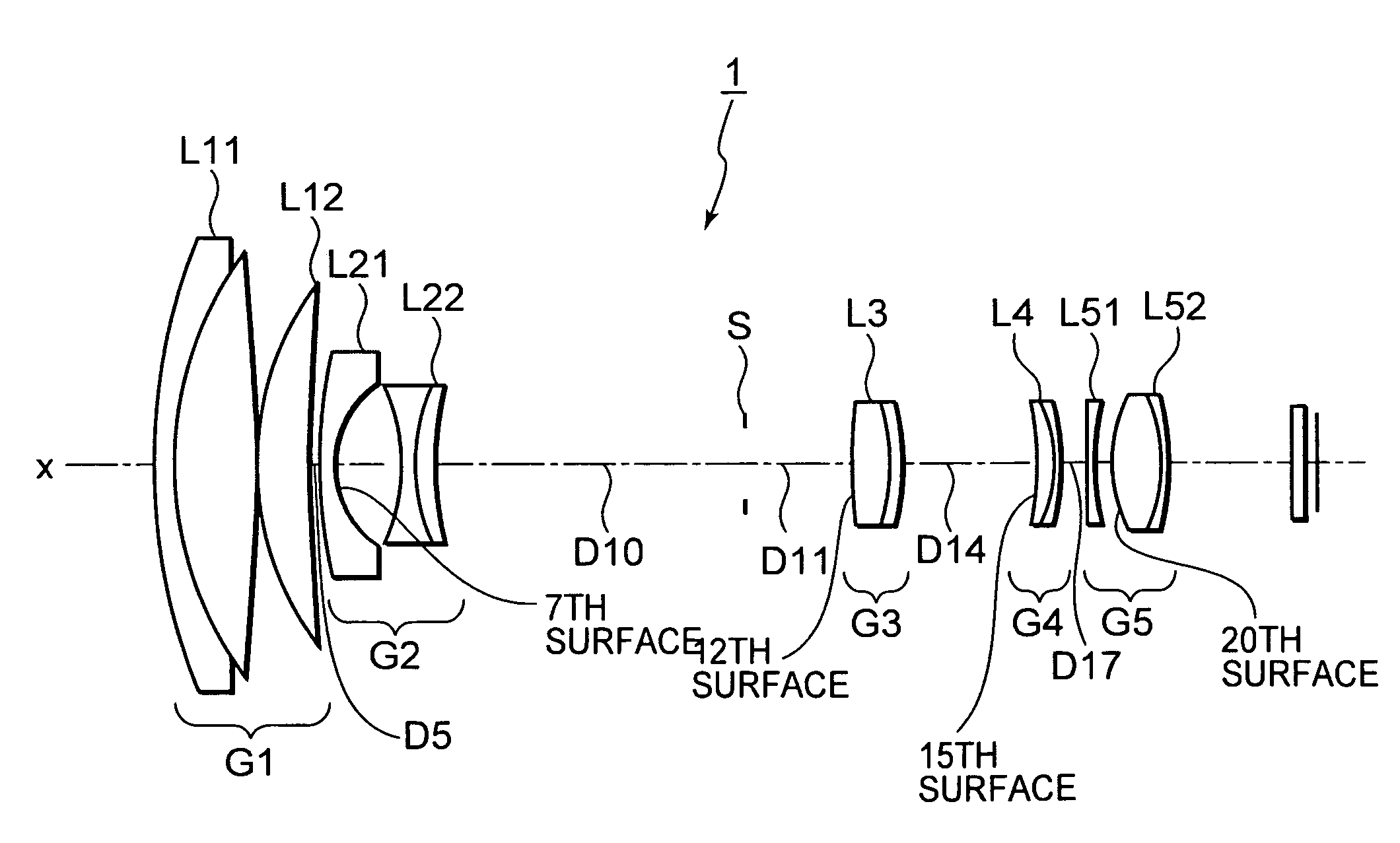
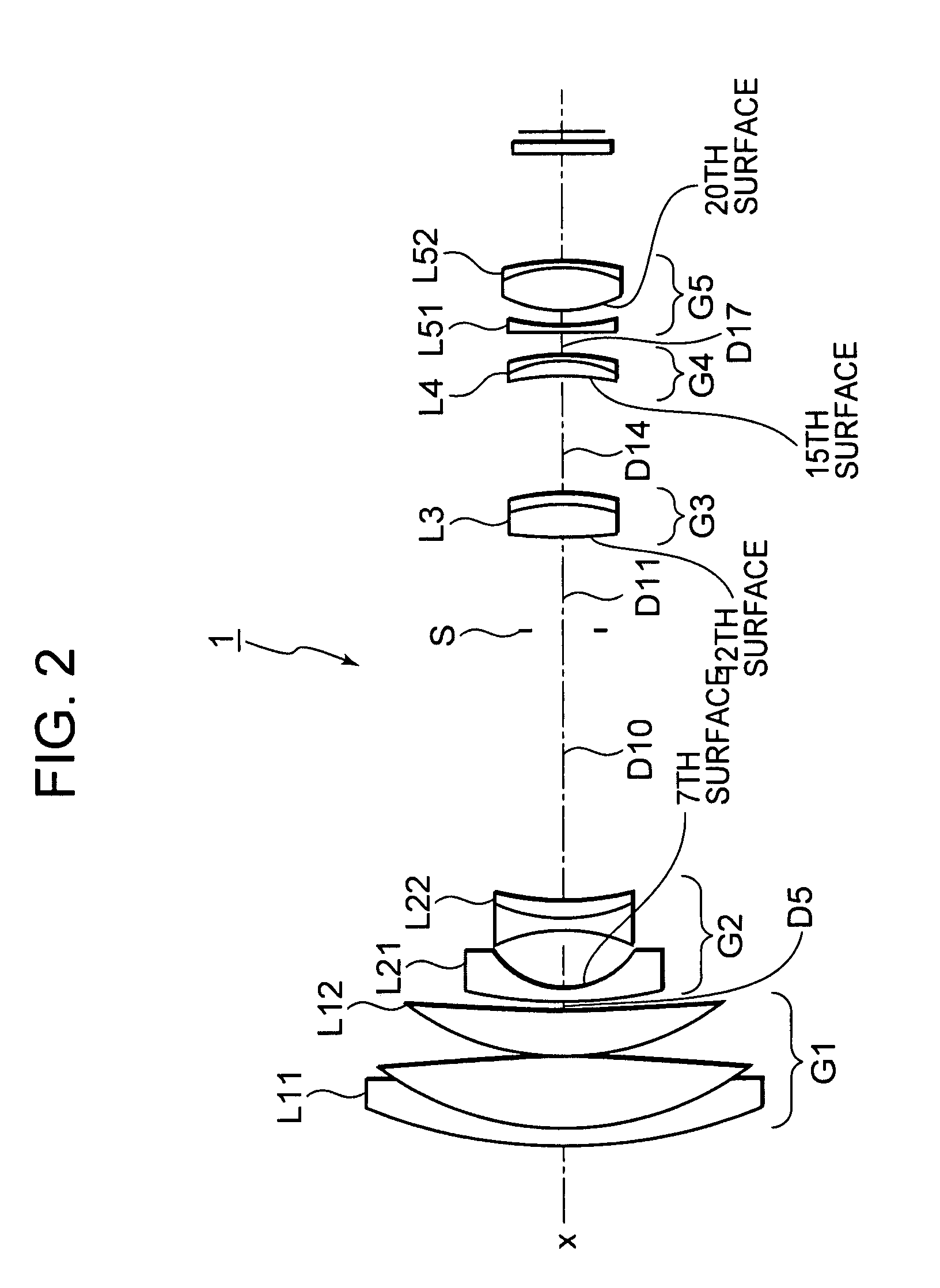
[0138]The seventh, twelfth, fifteenth and twentieth surfaces are aspherical. As such, the fourth- (A), sixth- (B), eighth- (C) and tenth-order (D) aspheric coefficients of these surfaces in numerical embodiment 1 are shown in table 2 along with their conic constants (κ). It is noted that in table 2 and the subsequent tables showing the aspherical coefficients, “E−i” is an exponential notation to base 10, in other words, “E-i” represents “10−i”, and, “0.12345E-05” represents, for example, “0.12345×10⁻⁵”.

[0139]

TABLE 2 7thκ = 0.000000A = −0.135737E-02B = −0.521916E-03C = −0.347911E-02D = +0.413344E-02Surface12thκ = 0.000000A = −0.673780E-02B = +0.479402E-02C = +0.796889E-02D = +0.458605E-02Surface15thκ = 0.000000A = −0.627487E-02B = −0.353678E-02C = +0.663879E-02D = −0.423531E-02Surface20thκ = 0.000000A = −0.117751E-01B = +0.335768E-02C = −0.409342E-02D = +0.140861E-02Surface

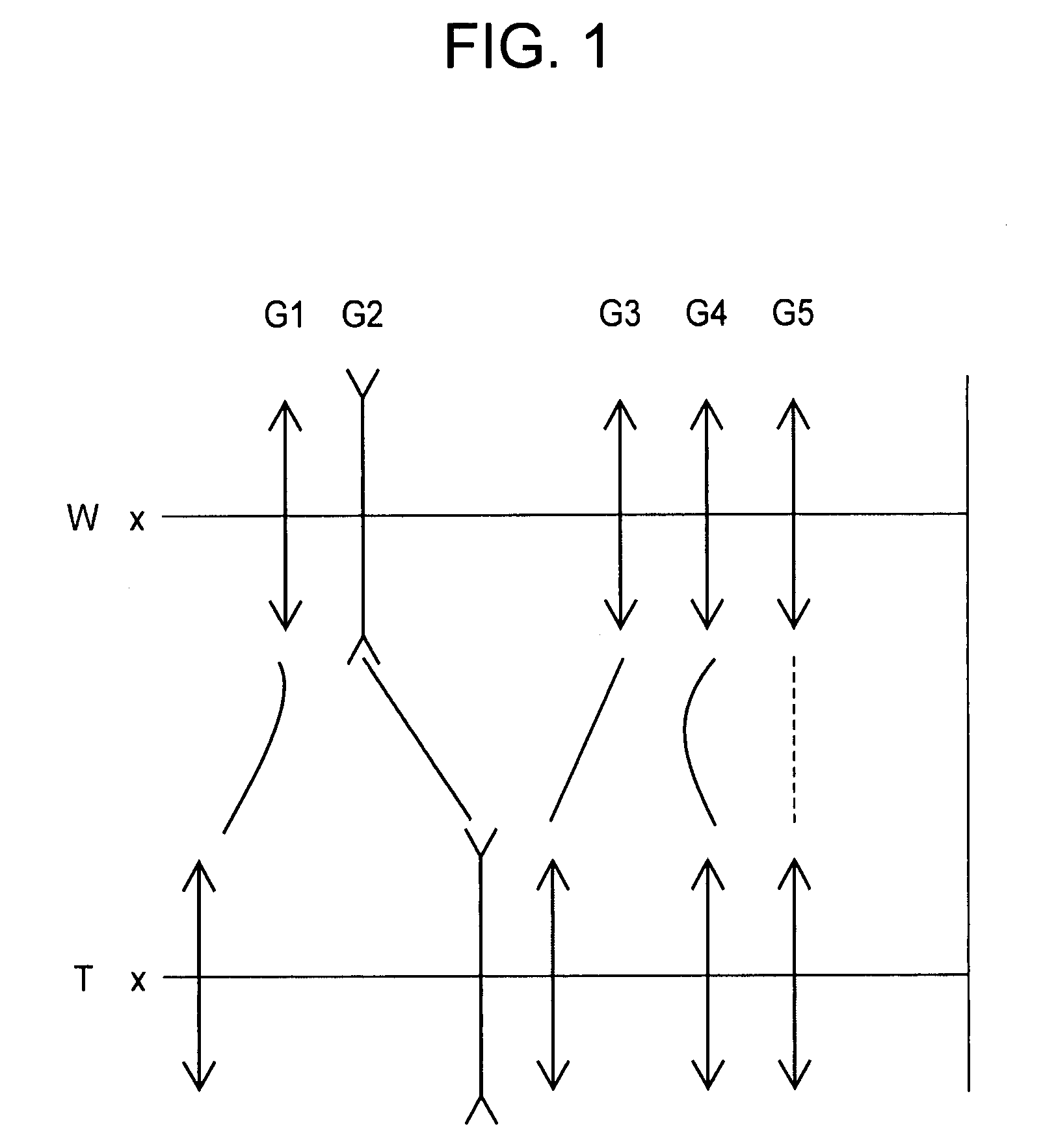
[0140]As the lens position state changes from the wide-angle end state to the telephoto end state, surface gap D...

embodiment 2

[0150]The seventh, twelfth, fifteenth and twentieth surfaces are all aspherical. As such, the fourth- (A), sixth- (B), eighth- (C) and tenth-order (D) aspheric coefficients of these surfaces in numerical embodiment 2 are shown in table 6 along with their conic constants (κ).

[0151]

TABLE 6 7thκ = 0.000000A = −0.195289E-02B = +0.996592E-03C = −0.452079E-02D = +0.348160E-02Surface12thκ = 0.000000A = −0.691555E-02B = +0.384528E-02C = −0.598708E-02D = +0.329867E-02Surface15thκ = 0.000000A = −0.679746E-02B = −0.111337E-02C = +0.190339E-02D = −0.118063E-02Surface20thκ = 0.000000A = −0.111597E-01B = +0.318369E-02C = −0.371284E-02D = +0.116364E-02Surface

[0152]As the lens position state changes from the wide-angle end state to the telephoto end state, surface gap D5 between the first lens group G1 and the second lens group G2, surface gap D10 between the second lens group G2 and the aperture stop S, surface gap D11 between the aperture stop S and the third lens group G3, surface gap D14 betwee...

embodiment 3

[0162]The eighth, thirteenth, sixteenth and twenty-first surfaces are all aspherical. As such, the fourth- (A), sixth- (B), eighth- (C) and tenth-order (D) aspheric coefficients of these surfaces in numerical embodiment 3 are shown in table 10 along with their conic constants (κ).

[0163]

TABLE 10 8thκ = 0.000000A = −0.434984E-03B = +0.572353E-02C = −0.126050E-01D = +0.978155E-02Surface19thκ = 0.000000A = −0.689014E-02B = +0.425011E-02C = −0.697951E-02D = +0.398211E-02Surface16thκ = 0.000000A = −0.755406E-02B = −0.208868E-02C = +0.370596E-02D = −0.231137E-02Surface21stκ = 0.000000A = −0.115363E-01B = +0.325661E-02C = −0.395446E-02D = +0.128002E-02Surface

[0164]As the lens position state changes from the wide-angle end state to the telephoto end state, surface gap D5 between the first lens group G1 and the second lens group G2, surface gap D11 between the second lens group G2 and the aperture stop S, surface gap D12 between the aperture stop S and the third lens group G3, surface gap D15...


PUM


Abstract

A variable focal length lens system includes: a first lens group having a positive refractive power; a second lens group having a negative refractive power; a third lens group having a positive refractive power; and a fourth lens group having a positive refractive power. As the lens position state changes from a wide-angle end state to a telephoto end state, at least each of the lens groups is mobile, the second lens group moves towards the image side and the third lens group moves towards the object side such that the gap between the first and the second lens group increases, and the gap between the second and the third lens group decreases, while the fourth lens group moves in the direction of the optical axis so as to compensate for changes in the position of the image plane which accompany movements of each of the lens group.

Description

CROSS REFERENCES TO RELATED APPLICATIONS[0001]The present application contains subject matter related to Japanese Patent Application JP 2006-120319 filed in the Japanese Patent Office on Apr. 25, 2006, the entire content of which being incorporated herein by reference.BACKGROUND OF THE INVENTION[0002]1. Field of the Invention[0003]The present invention relates to a new variable focal length lens system and imaging apparatus. More specifically, the present invention relates to a variable focal length lens system whose zoom ratio exceeds 10× and that is used in video cameras, digital still cameras and the like, as well as to an imaging apparatus equipped with the above-mentioned variable focal length lens system.[0004]2. Description of Related Art[0005]There is known a method of recording a subject image, which is formed by an imaging device, as a recording means in a camera, using such photoelectric transducers as CCDs (Charge Coupled Devices) or CMOSs (Complementary Metal-Oxide Semi...

Claims


Application Information

Patent Timeline
Patent Type & Authority Patents(United States)
IPC IPC(8): G02B9/34
CPCG02B15/173G02B15/144113G02B15/145129G02B15/22G02B13/009G02B3/0087G02B3/04G02B3/0062G02B15/1451G03B17/12G02B2003/0093H04N23/55
Inventor OHTAKE, MOTOYUKI
Owner SONY CORP
Why Eureka
Try Eureka