Composite dielectric and manufacturing method therefor

a dielectric and composite technology, applied in the field of dielectrics, can solve the problems of high dielectric constants, high dielectric loss, and difficult to use materials with high dielectric constants in high frequency bands, and achieve the effects of low dielectric loss characteristics, high dielectric constant, and superior characteristics

Active Publication Date: 2005-12-01
PANASONIC CORP
View PDF2 Cites 8 Cited by
  • Summary
  • Abstract
  • Description
  • Claims
  • Application Information

AI Technical Summary

Benefits of technology

[0084] As described above, because in the composite dielectric of the present invention conductive particles are distributed in a porous body of inorganic oxide, a high dielectric constant and low dielectric loss characteristics are achieved which have not been achieved with ceramic dielectrics and composite dielectrics using resin as the matrix. Namely, it is possible to achieve superior characteristics of 1) a relative dielectric constant εr of the dielectric in high frequency bands of 1 GHz or more of 4 or more, and 2) a dielectric loss tan δ of the dielectric in high frequency bands of 1 GHz or more of 2×10⁻⁴ or less. In this way it is possible to contribute greatly to miniaturization and high performance of electronic circuits.
[0085] More specifically, through the use of a porous body of inorganic oxide as a dielectric having electrical characteristics close to those of air in a configuration wherein conductive particles are dispersed in a dielectric matrix, it is possible with the composite dielectric of the present invention for particles to be dispersed and fixed as they cannot be in air and for the electrical insulation among the conductive particles, which is inadequate when resin is used, to be increased. In this configuration leakage current can be controlled, and a composite dielectric can be produced with low dielectric loss.
[0086] Moreover, because when conductive particles are packed at high densities it is possible to increase the dielectric constant of the composite dielectric while maintaining low dielectric loss, a composite dielectric can be provided having both a high dielectric constant and low dielectric loss, that has been impossible to achieve with ceramic dielectrics and dielectrics using resin as the matrix.
[0087] The composite dielectric of the present invention is particularly effective as a dielectric for use in microwave, millimeter wave and other high frequency bands. Consequently, it can be used in portable phones, millimeter wave wireless LANs, high-frequency signal transmitters, GPS, satellite communications devices and various other electronic devices.

Problems solved by technology

However, those ceramic materials developed up till now which have high dielectric constants also have high dielectric loss.
Consequently, it has been difficult to use materials with high dielectric constants in high frequency bands.
In a composite dielectric, however, dielectric loss may also occur because of electrical contact among the dispersed particles via the matrix.
This is difficult to avoid even if a material with high resistivity is used as the matrix.
Moreover, the dielectric loss of the matrix material itself also contributes to the dielectric loss of the composite dielectric.
Therefore, an ideal composite dielectric could be formed if air could be used as the matrix, but it is impossible to disperse and fix particles in air.

Method used


Image

  • Composite dielectric and manufacturing method therefor
  • Composite dielectric and manufacturing method therefor
  • Composite dielectric and manufacturing method therefor

Examples


embodiment 1

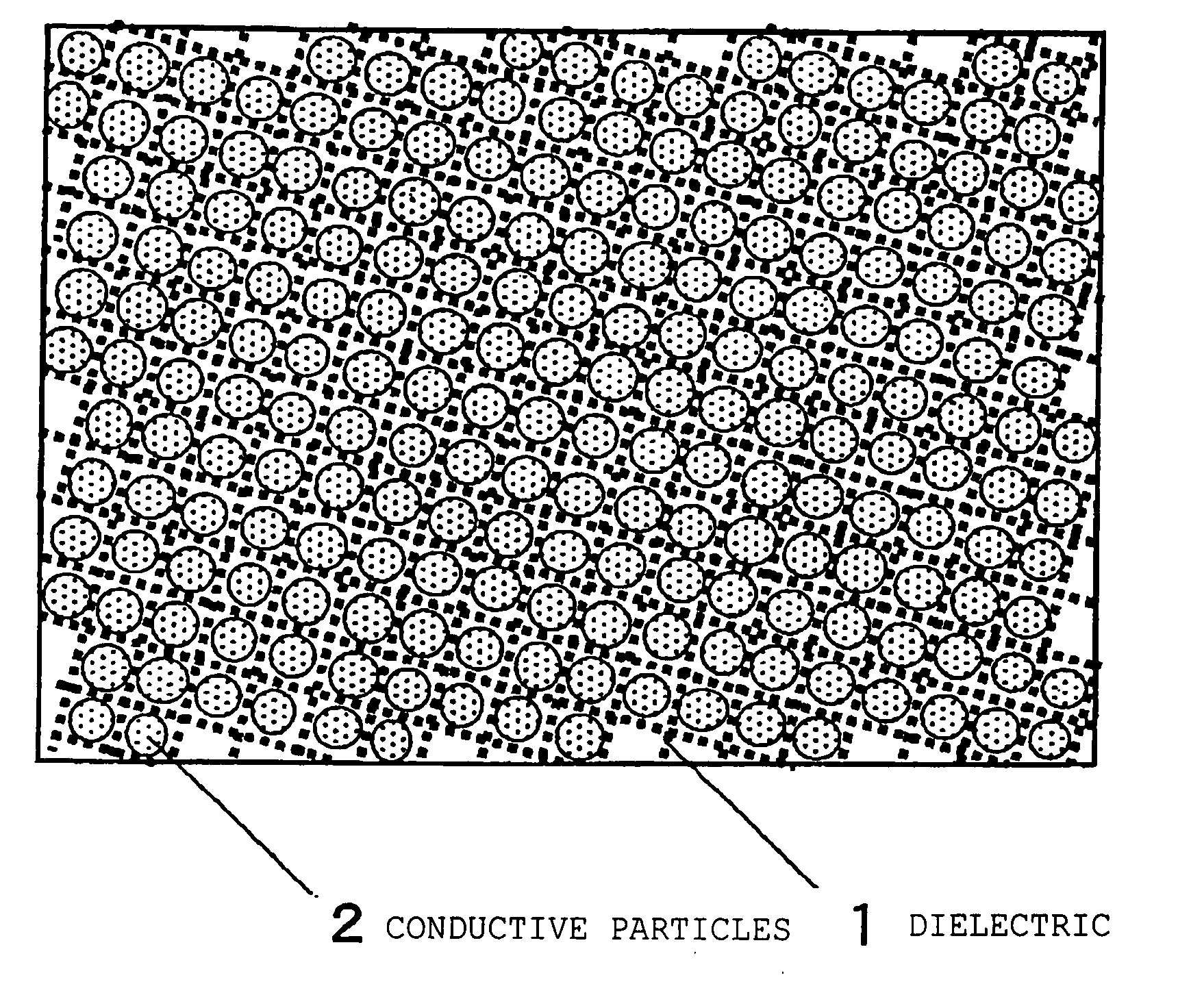
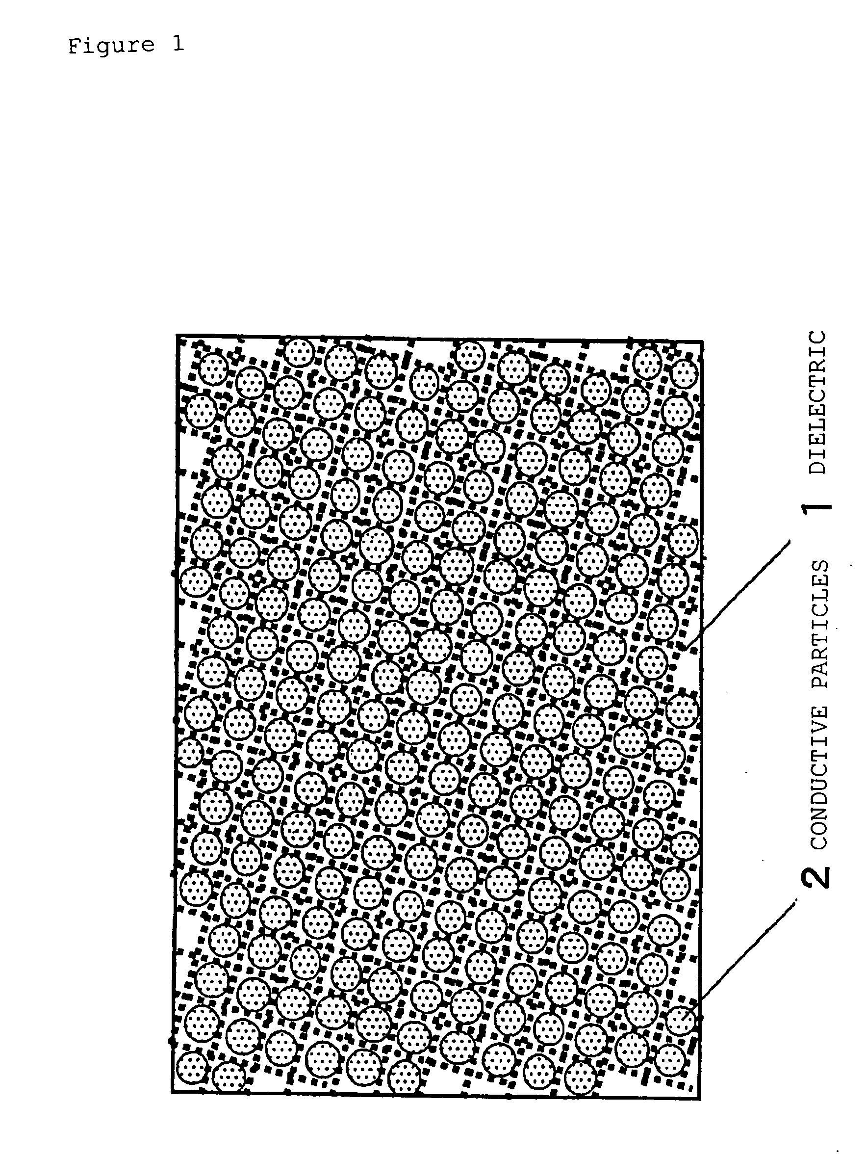
[0043] The composite dielectric of the present invention is explained using FIG. 1. FIG. 1 is a figure explaining an example of the composite dielectric of the present invention, which consists of dielectric 1 and conductive particles 2 which are dispersed in dielectric 1. A porous body is preferably used as dielectric 1. Using a porous body allows the apparent resistivity to be increased over that of a bulk material having the same composition.

[0044] When a porous body of porosity v is sliced on any surface, the proportion of cross-sectional area S0 occupied by the framework appearing on the surface (area s) is statistically s / S0=(1−v)2 / 3. Thus, if the resistivity of the material forming the porous body is ρ0, the apparent resistivity ρ of this porous body is expressed as ρ=ρ0 / (1−v)2 / 3. It is thus possible to form a matrix having a higher resistivity than the bulk material, thereby reducing leakage current and providing a composite dielectric with low dielectric loss.

[0045] Silic...

embodiment 2

[0053] In a second embodiment of the present invention, a dry gel is used for the porous body of the first embodiment.

[0054] In the porous body of the present invention, it is desirable from the standpoint of dispersibility, support of the particles and formation of spaces between particles at high packing densities to use a material with many nanometer size pores and nanometer size structures. One such desirable material is a dry gel obtained by the sol-gel method.

[0055] A dry gel is a porous body formed by a sol-gel reaction, which is formed by drying to remove the solvent from a wet gel composed of a solid skeleton solidified by reaction of a starting solution for the gel and containing a solvent. The dry gel is a nanopore material wherein continuous pores having a mean diameter in the range of a few 100 nanometers or less are formed by means of a solid skeleton composed of particles 100 nm or less in size. By minimizing the solid components it is possible to achieve an extreme...

embodiment 3

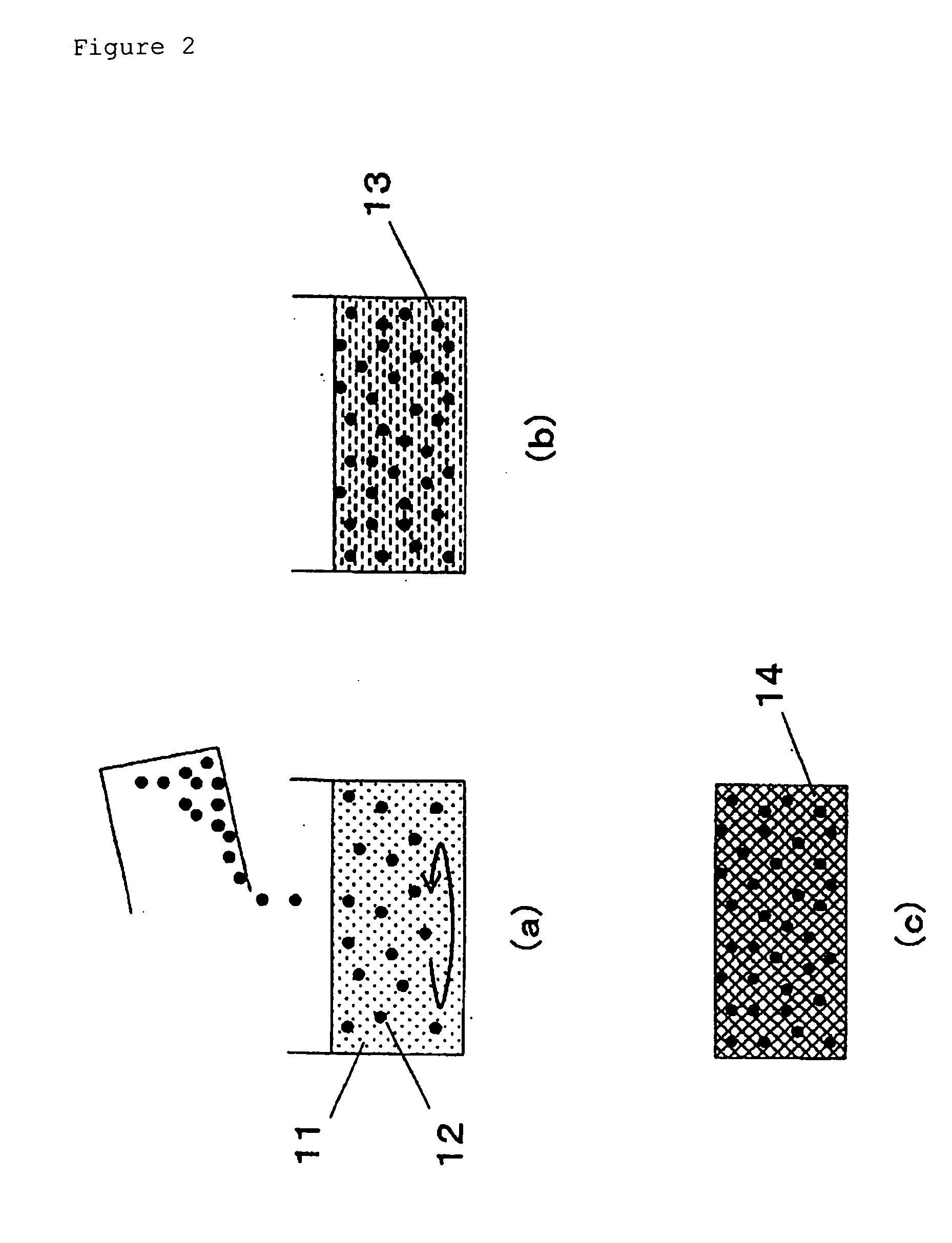
[0080] An embodiment of the manufacturing method of the present invention is explained using FIG. 2.

[0081] Conductive particles 12 are added to gel stock solution 11, which was prepared with a specific composition, and dispersed by agitation. Because the permeability of gel starting solution 11 is high as long as its viscosity is low, the solution permeates the spaces between conductive particles 12. As the solution permeating these spaces gels, a porous body forms between conductive particles 12, insulating conductive particles 12 from each other. The particles are uniformly distributed within the solution by continuous agitation until the viscosity of the solution rises enough to slow down the sedimentation velocity of conductive particles 12 sufficiently. Gelation is completed with the solution maintained in the same state to produce wet gel 13, which is dried to obtain dry gel 14, wherein the particles are insulated from one another and are uniformly distributed. Due to this co...


PUM

PropertyMeasurementUnit
relative dielectric constant εraaaaaaaaaa
porosityaaaaaaaaaa
densityaaaaaaaaaa

Abstract

It is a principal object of the present invention to provide a dielectric having a high relative dielectric constant and dielectric loss minimized in high frequency bands. That is, the present invention relates to a composite dielectric comprising conductive particles dispersed in a porous body of inorganic oxide, wherein 1) the relative dielectric constant εr of the dielectric in high frequency bands of 1 GHz or more is 4 or more, and 2) the dielectric loss tans of the dielectric in high frequency bands of 1 GHz or more is 2×10⁻⁴ or less, and to a manufacturing method therefor.

Description

TECHNICAL FIELD [0001] The present invention relates to an electronic circuit element. More specifically, the present invention relates to a dielectric for use particularly in microwave, millimeter wave and other high frequency bands. BACKGROUND ART [0002] For the dielectrics used in electronic circuit elements, ceramics have conventionally been used as materials with a dielectric constant of about 10 or more. Using a material with a high dielectric constant allows the electronic circuit element to be miniaturized. It also has the advantage of reducing radiation loss because in the microwave, millimeter wave and other high frequency bands electromagnetic energy becomes concentrated in the dielectric. Application of ceramics to microwave communications devices has expanded in recent years, and materials with high dielectric constants and low dielectric loss are being developed. [0003] A composite dielectric of conductive powder mixed with resin has been presented as a non-ceramic mat...

Claims


Application Information

Patent Timeline
Patent Type & Authority Applications(United States)
IPC IPC(8): C04B35/14C04B35/624C04B38/00H01B1/00H01B3/00H01B3/02
CPCC04B35/14C04B35/624C04B2235/80C04B2235/77C04B2235/5436C04B35/62655C04B38/0045C04B2111/90C04B2201/30C04B2235/3201C04B2235/3217C04B2235/422C04B35/10C04B38/0054Y10T428/249953Y10T428/249954Y10T428/249955Y10T428/249956Y10T428/249957
Inventor KUDOH, YUJIHASHIDA, TAKASHISUZUKI, MASA-AKI
Owner PANASONIC CORP
Why Eureka
Try Eureka