High-speed clock and data recovery circuit

Inactive Publication Date: 2007-10-23
RGT UNIV OF CALIFORNIA
View PDF11 Cites 19 Cited by
  • Summary
  • Abstract
  • Description
  • Claims
  • Application Information

AI Technical Summary

Problems solved by technology

Clock and data recovery (CDR) circuits operating at tens of gigabits per second pose diffi

Method used


Image

  • High-speed clock and data recovery circuit
  • High-speed clock and data recovery circuit
  • High-speed clock and data recovery circuit

Examples


Embodiment Construction

[0023]In the following description, reference is made to the accompanying drawings which form a part hereof, and which is shown, by way of illustration, several embodiments of the present invention. It is understood that other embodiments may be utilized and structural changes may be made without departing from the scope of the present invention.

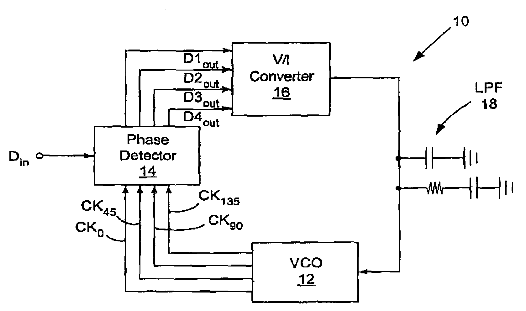
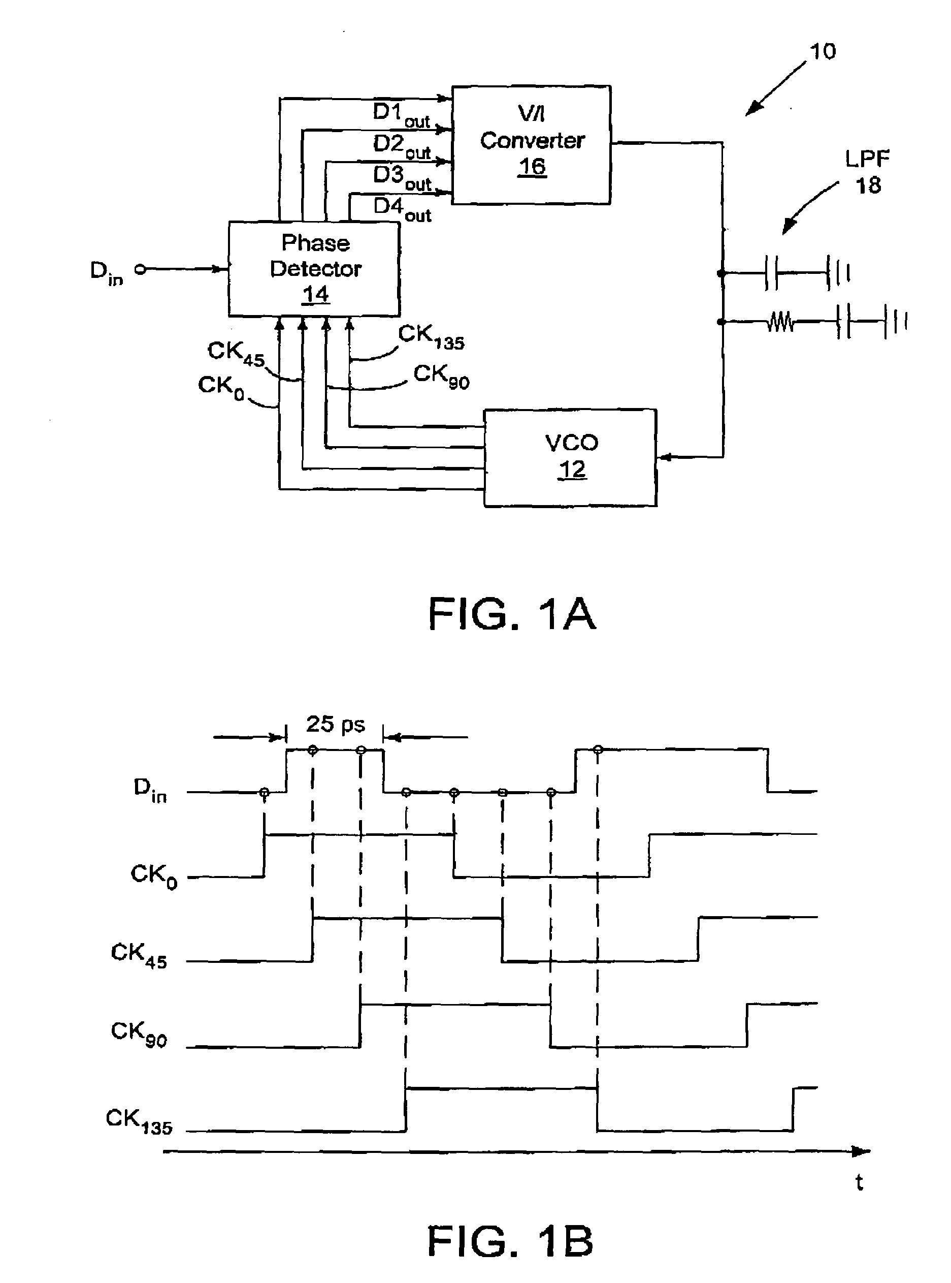
[0024]FIG 1A is a block diagram that illustrates the architecture of a clock and data recovery (CDR) circuit 10 according to the preferred embodiment of the present invention. The CDR circuit 10 includes: (1) a multi-phase voltage-controlled oscillator (VCO) 12 for accepting a control signal and for changing a frequency of a clock signal output from the VCO 12 in response thereto, wherein the VCO 12 outputs a plurality of phases of the clock signal; (2) a quarter-rare phase detector (PD) 14 for sampling an input data signal using the phases of the clock signal received from the VCO 12 and generating a plurality of output data signals in resp...


PUM


Abstract

A 40-Gb/s clock and data recovery (CDR) circuit incorporates a quarter-rate phase detector and a multi-phase voltage controlled oscillator to re-time and de-multiplex a 40-Gb/s input data signal into four 10-Gb/s output data signals. The circuit is fabricated in 0.18 μm CMOS technology.

Description

CROSS-REFERENCE TO RELATED APPLICATIONS[0001]This application claims priority under 35 U.S.C. § 119(e) to co-pending and commonly-assigned Provisional Application Ser. No. 60 / 445,722, entitled “A 40-GB / S CLOCK AND DATA RECOVERY CIRCUIT IN 0.18 MM CMOS TECHNOLOGY,” filed on Feb. 7, 2003, by Jri Lee and Behzad Razavi, which application is incorporated by reference herein.BACKGROUND OF THE INVENTION[0002]1. Field of the Invention[0003]The present invention relates generally to 40-Gb / s data, and in particular, to a 40-Gb / s clock and data recovery circuit in 0.18 μm CMOS technology.[0004]2. Description of the Related Art[0005](Note: This application references a number of different publications as indicated throughout the specification by reference numbers enclosed in brackets, e.g., [x]. A list of these different publications ordered according to these reference numbers can be found below in the section entitled “References.” Each of these publications is incorporated by reference herei...

Claims


Application Information

Patent Timeline
IPC IPC(8): H03D3/24H03K3/3562H03K3/86H03K5/00H03K5/01H03K5/14H03K19/21H03L7/091H03L7/099H04L7/033H04N
CPCH03K3/3562H03K3/86H03K5/14H04L7/033H03L7/091H03L7/0995H03K19/215H03K2005/00032
Inventor LEE, JRIRAZAVI, BEHZAD
Owner RGT UNIV OF CALIFORNIA
Why Eureka
Try Eureka