Method and apparatus for reducing contamination of an electrical signal

Active Publication Date: 2007-10-23
RGT UNIV OF CALIFORNIA
View PDF22 Cites 190 Cited by
  • Summary
  • Abstract
  • Description
  • Claims
  • Application Information

AI Technical Summary

Benefits of technology

[0006]To overcome the limitations in the prior art described above, and to overcome other limitations that will become apparent upon reading and understanding the present specification, the invention provides a method of reducing contamination of electrical signals recorded in the presence of repeated int

Problems solved by technology

The interference can also comprise interference

Method used


Image

  • Method and apparatus for reducing contamination of an electrical signal
  • Method and apparatus for reducing contamination of an electrical signal
  • Method and apparatus for reducing contamination of an electrical signal

Examples


example 1

Acquiring Simultaneous EEG and Functional MRI

Methods

EEG Device and Lead Placement

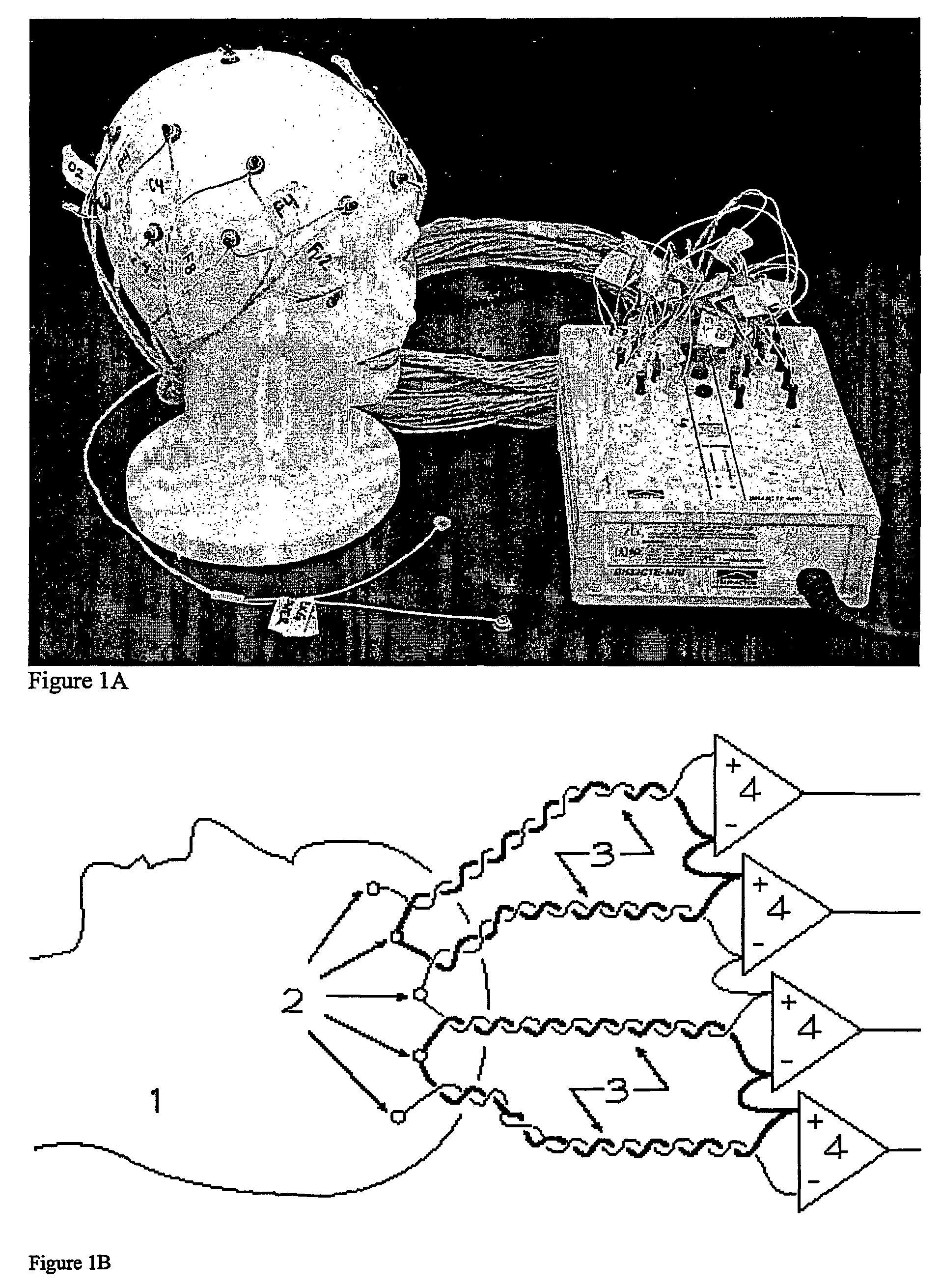
[0104]The EEG device incorporates numerous hardware modifications to reduce artifact in concurrent EEG / fMRI, and was provided by Telefactor Corporation (W. Conshohocken, Pa.). Signal is detected from the, scalp using silver chloride plated plastic cup electrodes connected to a compact magnet-compatible local amplifier (headbox) via 10 foot carbon fiber leads with a resistance of 1 kΩ / foot. This design minimized both artifact in the MR images and the induction of RF current loops in the lead wires.

[0105]A lead configuration was devised that minimized unwanted current induction by recording EEG in a hard-wired montage using special dual lead electrodes. The lead wires from each electrode pair were twisted together over their entire length, forming a chained bipolar montage for each hemisphere (fp2-f8, f8-t4, t4-t6, t6-o2, o2-p4,p4-c4, c4-f4, f4-fp2; fp1-f7, f7-t3, t3-t5, t5-o1, o1-p3, p3-c3, c3-f3, f3-fp1...

example 2

Method for Removal of Artifacts in Simultaneous EEG and fMRI

[0129]The strategy outlined below is applicable to any method involving digital subtractive noise cancellation, including EEG, EEG / fMRI, as well as any environment in which subtracted averages of artifacts are used to reduce noise.

Methods

EEG Recording and Electrode Placement

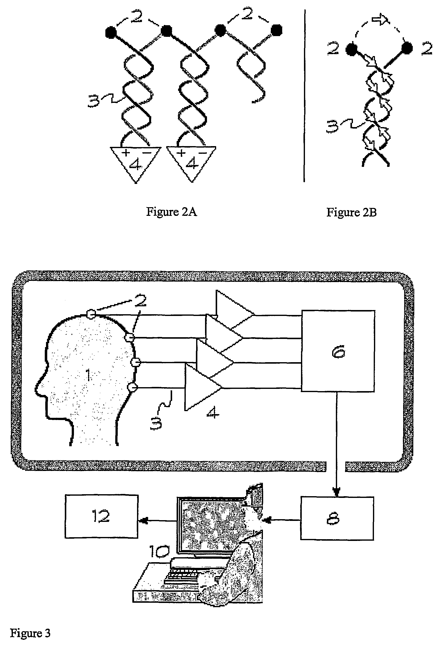
[0130]The basic approach of differential recording has been described previously (Goldman, Cohen et al. 2000; Goldman, Stern et al. 2000). Paired silver electrodes are placed on the scalp surface attached with conductive electrode gel and check to ensure that the nominal impedance is less than 5 kΩ for each electrode. The electrodes are themselves attached to two carbon fiber conductors having a distributed resistance of approximately 3 kΩ / m The wires are dressed in pairs with the leads from adjacent electrodes twisted together tightly to minimize electromagnetic pickup. This configuration offers about 6 dB attenuation of artifacts from gradient and ball...

example 3

Increasing Dynamic Range Available in Digitized Electro-Encephalographic Signals

[0153]The scalp electrical potentials used in the EEG contain both time varying and static (DC) components. Often the DC offset is much larger than the EEG, but it is seldom of interest for clinical diagnostic purposes, as it contains essentially no information. However, it does cause trouble as it increases the dynamic range needed to digitize the EEG signal. For example, the EEG may be only a few microVolts (μV), while potentials of several tens of milliVolts (mV) may exist between electrodes, or as a result of the chemical electrode potential developed when the electrode is in contact with the scalp. The depth of the signal digitization will be reduced by the ratio of the EEG to the DC potential: assuming a DC offset of 10 mV, an EEG signal of 10 μV, and a 12 bit analog to digital converter (ADC), the 4096 different levels representable by the ADC will be reduced to only 4 levels for the EEG. Clearly...


PUM


Abstract

The method of reducing contamination of electrical signals recorded in the presence of repeated interference contamination comprises obtaining an electrical signal recorded in the presence of a contaminating signal, and detecting a timing signal that occurs at a fixed time point during the electrical signal relative to the onset of the contaminating signal. The electrical signal is digitized, wherein the digitizing begins with the timing signal. A plurality of digitized electrical signals is analyzed, wherein the electrical signals are synchronized with respect to the timing signal, to obtain an estimated contaminating signal that is subtracted from the digitized electrical signal. This method can be used with electrophysiological signals, such as EEG, ECG, EMG and galvanic skin response, and for elimination of noise associated with concurrently used methods such as MRI. The method of noise reduction is applicable to recordings of other electrical signals, including audio recordings.

Description

[0001]This application claims the benefit of U.S. provisional patent application numbers 60 / 225,389, filed Aug. 15, 2000, and 60 / 267,337, filed Feb. 7, 2001, the entire contents of each of which are incorporated herein by reference. Throughout this application, various publications are referenced. The contents of these references are incorporated by reference herein, in order to describe more fully the state of the art.TECHNICAL FIELD OF THE INVENTION[0002]This invention relates generally to methods and apparatus for signal processing and data collection that are particularly suited for minimizing artifacts and optimizing signal-to-noise in simultaneous recording of electroencephalographic (EEG) and Magnetic Resonance Imaging R signals, as well as other environments in which electrical signals are subject to repeated interference. The methods of the invention can be applied to other recordings containing repeated electrical interference, including eletromyelographic (EMG), electroca...

Claims


Application Information

Patent Timeline
IPC IPC(8): A61B5/04G01R33/28A61B5/0476A61B5/055G06F17/00
CPCA61B5/04017A61B5/04004A61B5/4094A61B5/30A61B5/316
Inventor COHEN, MARK S.
Owner RGT UNIV OF CALIFORNIA
Why Eureka
Try Eureka