Tracking error detection apparatus including reduction in false tracking error detection during phase error detection

a tracking error detection and phase error detection technology, applied in the direction of data recording, instruments, disposition/mounting of heads, etc., can solve the problems of false detection, increase in recording density on a recording medium, and inability to achieve tracking error detection using analog signal processing, so as to reduce the influence of false detection and improve the accuracy of tracking error signals

Inactive Publication Date: 2007-10-30
PANASONIC HEALTHCARE HLDG CO LTD
View PDF18 Cites 9 Cited by
  • Summary
  • Abstract
  • Description
  • Claims
  • Application Information

AI Technical Summary

Benefits of technology

[0030]The present invention is made to solve the above-described problems and has for its object to provide a tracking error detection apparatus that can reduce influences of false detection during phase error detection to improve accuracy of a tracking error signal.
[0032]According to a first aspect of the present invention, a tracking error detection apparatus comprises: a photodetector comprising four photoreceptor elements which are partitioned along a tangential direction and a perpendicular direction with respect to an information track that is recorded as an information pit line on a recording medium; zerocross detection circuits for detecting zerocross points at which two sequences of digital signals intersect center levels of the respective digital signals, each of the two sequences of digital signals being obtained by adding output signals from the two photoreceptor elements positioned on a diagonal line, among four signals that are generated according to the amounts of light received by the respective photoreceptor elements and are outputted from the photodetector; a phase difference detection circuit for performing phase comparison using a distance between the zerocross points of the two sequences of digital signals, and limiting the result of phase comparison to a value under a first predetermined value when the result of phase comparison is larger than the first predetermined value; and a low-pass filter for performing band restriction to a signal outputted from the phase difference detection circuit, thereby to obtain a tracking error signal. Therefore, it is possible to reduce influences of false detection during phase error detection, thereby enhancing accuracy of the tracking error signal.
[0035]According to a fourth aspect of the present invention, a tracking error detection apparatus comprises: a photodetector comprising four photoreceptor elements which are partitioned along a tangential direction and a perpendicular direction with respect to an information track that is recorded as an information pit line on a recording medium; zerocross detection circuits for detecting zerocross points at which two sequences of digital signals intersect center levels of the respective digital signals, each of the two sequences of digital signals being obtained by adding output signals from the two photoreceptor elements positioned on a diagonal line, among four signals that are generated according to the amounts of light received by the respective photoreceptor elements and are outputted from the photodetector; an edge detection circuit for detecting the states of edges to be used for phase comparison, using binary signals of sampling data of the two sequences of digital signals; a phase difference detection circuit for performing phase comparison using a distance between the zerocross points of the two sequences of digital signals; and a low-pass filter for performing band restriction to the signal outputted from the phase difference detection circuit, thereby to obtain a tracking error signal; wherein the phase difference detection circuit judges whether the edges to be the targets of phase comparison are valid as edges for phase comparison or not on the basis of the states of the edges detected by the edge detection circuit, and does not carry out output / updation of the phase comparison result at the edges judged as “invalid”. Therefore, it is possible to reduce influences of false detection during phase error detection, thereby enhancing accuracy of the tracking error signal.
[0039]According to an eighth aspect of the present invention, a tracking error detection apparatus comprises: a photodetector comprising four photoreceptor elements which are partitioned along a tangential direction and a perpendicular direction with respect to an information track that is recorded as an information pit line on a recording medium; zerocross detection circuits for detecting zerocross points at which four sequences of digital signals intersect center levels of the respective digital signals, the four sequences of digital signals being generated according to the amounts of light received by the respective photoreceptor elements and are outputted from the photodetector; a first phase difference detection circuit for performing phase comparison using a distance between the zerocross points of two sequences of digital signals that are obtained from the photoreceptor elements positioned forward in the advancing direction of the information track, among the zerocross points of the four sequences of digital signals, and limiting the result of phase comparison to a value under the first predetermined value when the result of phase comparison is larger than the first predetermined value; and a second phase difference detection circuit for performing phase comparison using a distance between the zerocross points of two sequences of digital signals that are obtained from the photoreceptor elements positioned backward in the advancing direction of the information track, among the zerocross points of the four sequences of digital signals, and limiting the result of phase comparison to a value under the first predetermined value when the result of phase comparison is larger than the first predetermined value; an addition circuit for adding the output signals of the first and second phase difference detection circuits; and a low-pass filter for performing band restriction to the signal outputted from the addition circuit, thereby to obtain a tracking error signal. Therefore, it is possible to reduce influences of false detection during phase error detection, thereby enhancing accuracy of the tracking error signal. Further, no offset that depends on the depth of the pit carved in the disc occurs, thereby producing an accurate tracking error signal.

Problems solved by technology

As described above, since the conventional tracking error detection apparatus can detect a tracking error by digital signal processing, it can deal with speedup of an optical recording / playback apparatus and an increase in recording density on a recording medium, which cannot be achieved by tracking error detection using analog signal processing.
In the above-mentioned conventional tracking error detection apparatus, however, when the amplitude of the analog signal inputted to the first and second ADCs 104a and 104b cannot be sufficiently obtained due to a defect or the like, or when the analog signal has a noise, the first and second zerocross point detection circuits 106a and 106b incorrectly detect zerocross points, resulting in false detection of the phase difference detection circuit 107.
The phase comparison output which is generated by the data updation unit 3 of the phase difference detection circuit 107 using such phase comparison result undesirably becomes a phase difference signal having a large value as shown in FIG. 14, resulting in degradation in accuracy of the tracking error signal that is generated by performing band restriction with the LPF 108.

Method used


Image

  • Tracking error detection apparatus including reduction in false tracking error detection during phase error detection
  • Tracking error detection apparatus including reduction in false tracking error detection during phase error detection
  • Tracking error detection apparatus including reduction in false tracking error detection during phase error detection

Examples


embodiment 1

[0060]Hereinafter, a tracking error detection apparatus according to a first embodiment of the present invention will be described with reference to FIGS. 1 and 2.

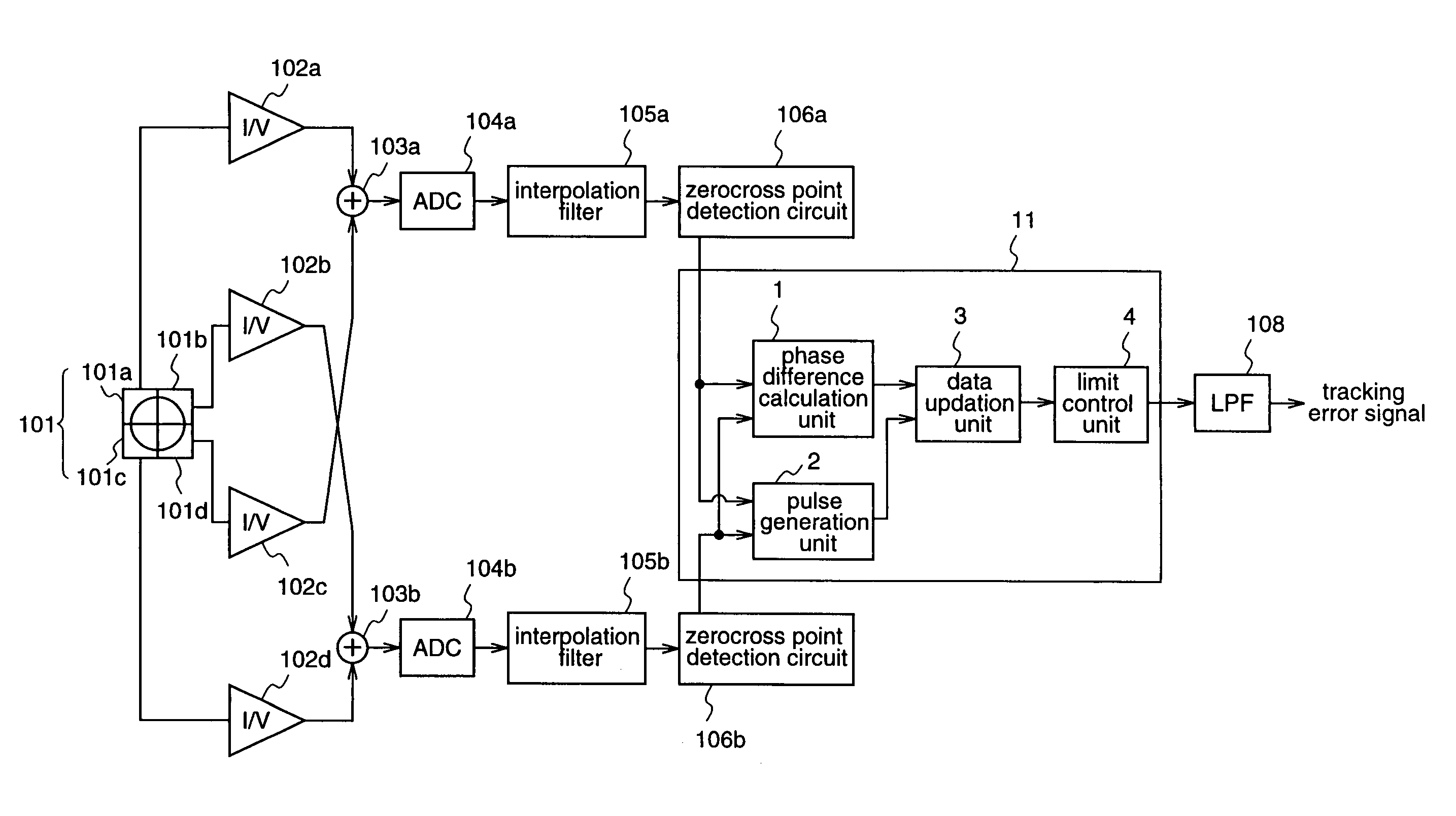
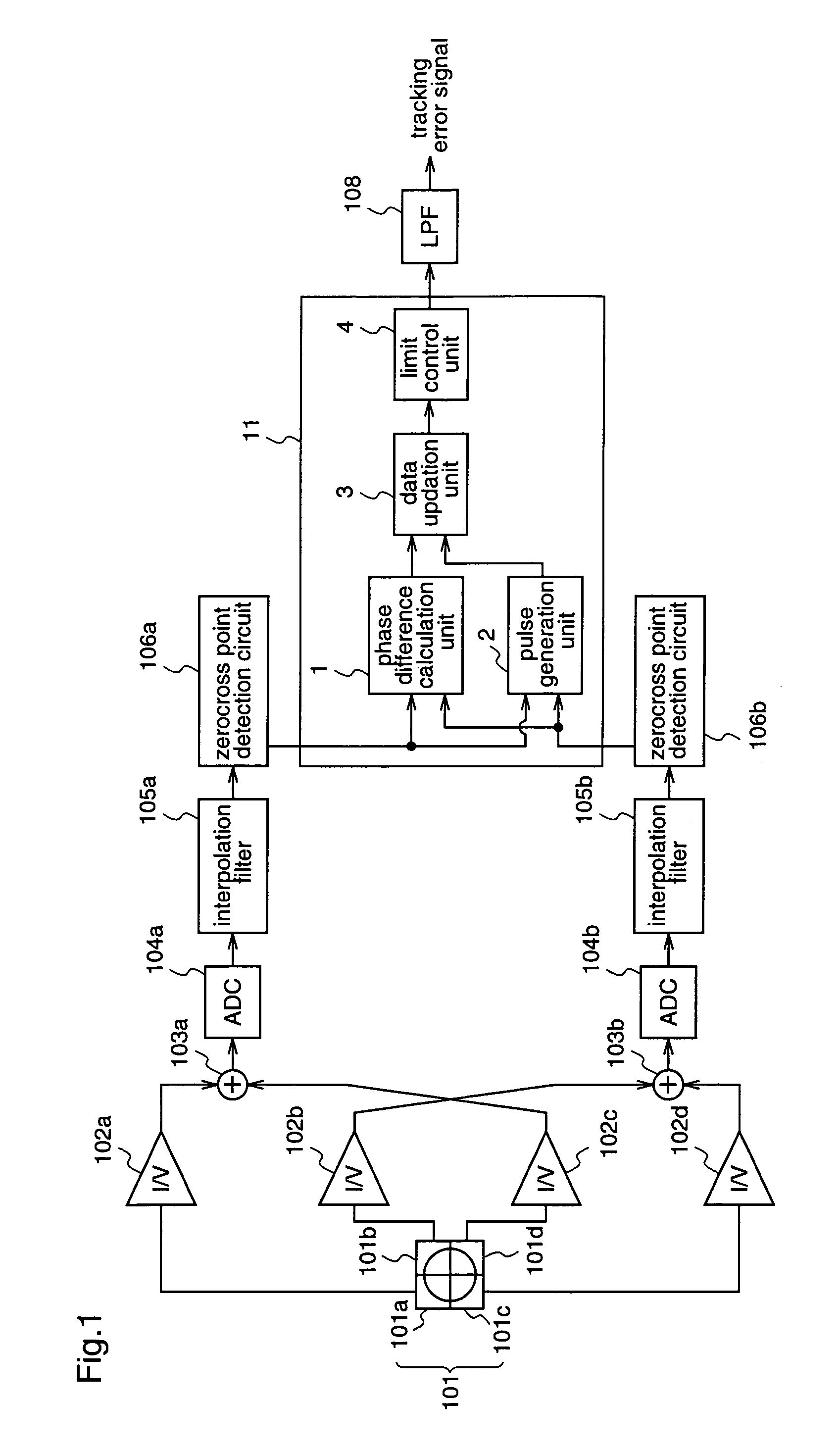
[0061]FIG. 1 is a block diagram illustrating an example of a tracking error detection apparatus according to the first embodiment.

[0062]In FIG. 1, the tracking error detection apparatus according to the first embodiment comprises a photodetector 101, current-to-voltage converters 102a to 102d, first and second adders 103a and 103b as signal generators for generating two signal sequences, first and second analog-to-digital converters (ADC) 104a and 104b, first and second interpolation filters 105a and 105b, first and second zerocross point detection circuits 106a and 106b, a phase difference detection circuit 11, and a low-pass filter (LPF) 108. Since the constituents of the tracking error detection apparatus according to the first embodiment other than the phase difference detection circuit 11 are identical to those of the...

embodiment 2

[0078]Hereinafter, a tracking error detection apparatus according to a second embodiment of the present invention will be described.

[0079]FIG. 4 is a block diagram illustrating an example of a tracking error detection apparatus according to the second embodiment.

[0080]In FIG. 4, the tracking error detection apparatus comprises a photodetector 101, current-to-voltage converters 102a to 102d, first and second adders 103a and 103b, first and second analog-to-digital converters (ADC) 104a and 104b, an edge detection circuit 21, first and second interpolation filters 105a and 105b, first and second zerocross point detection circuits 106a and 106b, a phase difference detection circuit 22, and a low-pass filter (LPF) 108. Since the constituents of the tracking error detection apparatus according to the second embodiment other than the edge detection circuit 21 and the phase difference detection circuit 22 are identical to those of the conventional tracking error detection apparatus describ...

embodiment 3

[0098]Hereinafter, a tracking error detection apparatus according to a third embodiment of the present invention will be described.

[0099]FIG. 7 is a block diagram illustrating an example of a tracking error detection apparatus according to the third embodiment.

[0100]In FIG. 7, the tracking error detection apparatus comprises a photodetector 101 that has photoreceptor elements 101a, 101b, 101c, and 101d each receiving a reflected light beam from a light spot, and outputs photo currents according to the amounts of light received by the respective photoreceptor elements; first to fourth current-to-voltage converter 102a to 102d for converting the photo currents outputted from the photodetector 101 into voltage signals; first to fourth analog-to-digital converters (ADCs) 104a to 104d for obtaining first to fourth digital signal sequences from the voltage signals obtained by the first to fourth current-to-voltage converters 102a to 102d; first to fourth interpolation filters 105a to 105d...


PUM

PropertyMeasurementUnit
lengthaaaaaaaaaa
lengthaaaaaaaaaa
distanceaaaaaaaaaa

Abstract

A tracking error detection apparatus comprises a photodetector comprising plural photoreceptor elements; zerocross detection circuits for detecting zerocross points at which two sequences of digital signals intersect the center levels of the respective digital signals, which digital signals are generated according to the amounts of light received by the respective photoreceptor elements and are outputted from the photodetector; a phase difference detection circuit for performing phase comparison using a distance between zerocross points of the two sequences of digital signals, and outputting a result of phase comparison; and a low-pass filter for performing band restriction to a signal outputted from the phase difference detection circuit. When a phase difference between the two sequences of digital signals, which is detected by the phase difference detection circuit, is larger than a maximum value of a theoretical tracking error signal, the output from the phase difference detection circuit is limited.

Description

FIELD OF THE INVENTION[0001]The present invention relates to a tracking error detection apparatus for detecting a tracking error of a light spot that is obtained by irradiating an optical recording medium with a light beam.BACKGROUND OF THE INVENTION[0002]In recent years, a technique called “phase difference method” has been employed as a method for obtaining a tracking control signal from an optical disc on which information is recorded by projecting and depressing pits, such as a CD (Compact Disc) or a DVD (Digital Video Disc).[0003]Japanese Published Patent Application No. Hei.2001-67690 discloses an example of such phase difference method.[0004]Hereinafter, a conventional tracking error detection apparatus disclosed in Japanese Published Patent Application No. Hei.2001-67690 will be described with reference to FIG. 10.[0005]FIG. 10 is a block diagram illustrating the construction of the conventional tracking error detection apparatus.[0006]As shown in FIG. 10, the conventional t...

Claims


Application Information

Patent Timeline
Patent Type & Authority Patents(United States)
IPC IPC(8): G11B7/00G11B7/09
CPCG11B7/0906G11B7/09
Inventor HIRATSUKA, TAKASHIGE
Owner PANASONIC HEALTHCARE HLDG CO LTD
Why Eureka
Try Eureka