Power control for non-constant envelope modulation

a power control and non-constant envelope technology, applied in power management, transmission monitoring, wireless communication, etc., can solve the problems of inability to correct the control loop, transients at the end of the burst, and inability to achieve the correctness of the control loop, so as to reduce the bandwidth of the control system

Inactive Publication Date: 2007-10-30
NOKIA SOLUTIONS & NETWORKS OY
View PDF12 Cites 6 Cited by
  • Summary
  • Abstract
  • Description
  • Claims
  • Application Information

AI Technical Summary

Benefits of technology

[0012]The present invention provides a technique for control of transmitter power which preserves modulation characteristics, and which is thus particularly advantageous when utilised in systems with non-constant modulation schemes. This improvement is achieved by combining the power level control signal with the modulation envelope of the modulated RF carrier signal during a transmission burst. Further improvement may be obtained by reducing the bandwidth of the control system during the burst.

Problems solved by technology

A disadvantage of conventional power control loops is illustrated in FIG. 1(b). FIG. 1(b) depicts a graph of the power output of a power amplifier transmitting a non-constant envelope modulated burst, such as an AM burst.
Such a situation is unacceptable for advanced wireless transmissions using AM.
However, FIG. 1(b) illustrates a disadvantage of this approach when applied to advanced modulation schemes, known as gain tilt.
Because of the problems that arise in the power control loop due to non-constant envelop modulation, in prior art techniques it has generally been possible only to operate in open-loop mode during the operational cycle, or to use only a very low control loop-bandwidth during the operational cycle.
Firstly, the power control loop is unable to correct for gain variations over the burst, Secondly, because of the slow averaging, certain data patterns can cause transients at the end of the burst when restoring loop-bandwidth just prior to ramp-down.
One potential problem with the technique disclosed in WO 01 / 03292 is that there may be a small offset associated with the sample-and-hold circuit.

Method used


Image

  • Power control for non-constant envelope modulation
  • Power control for non-constant envelope modulation
  • Power control for non-constant envelope modulation

Examples


Embodiment Construction

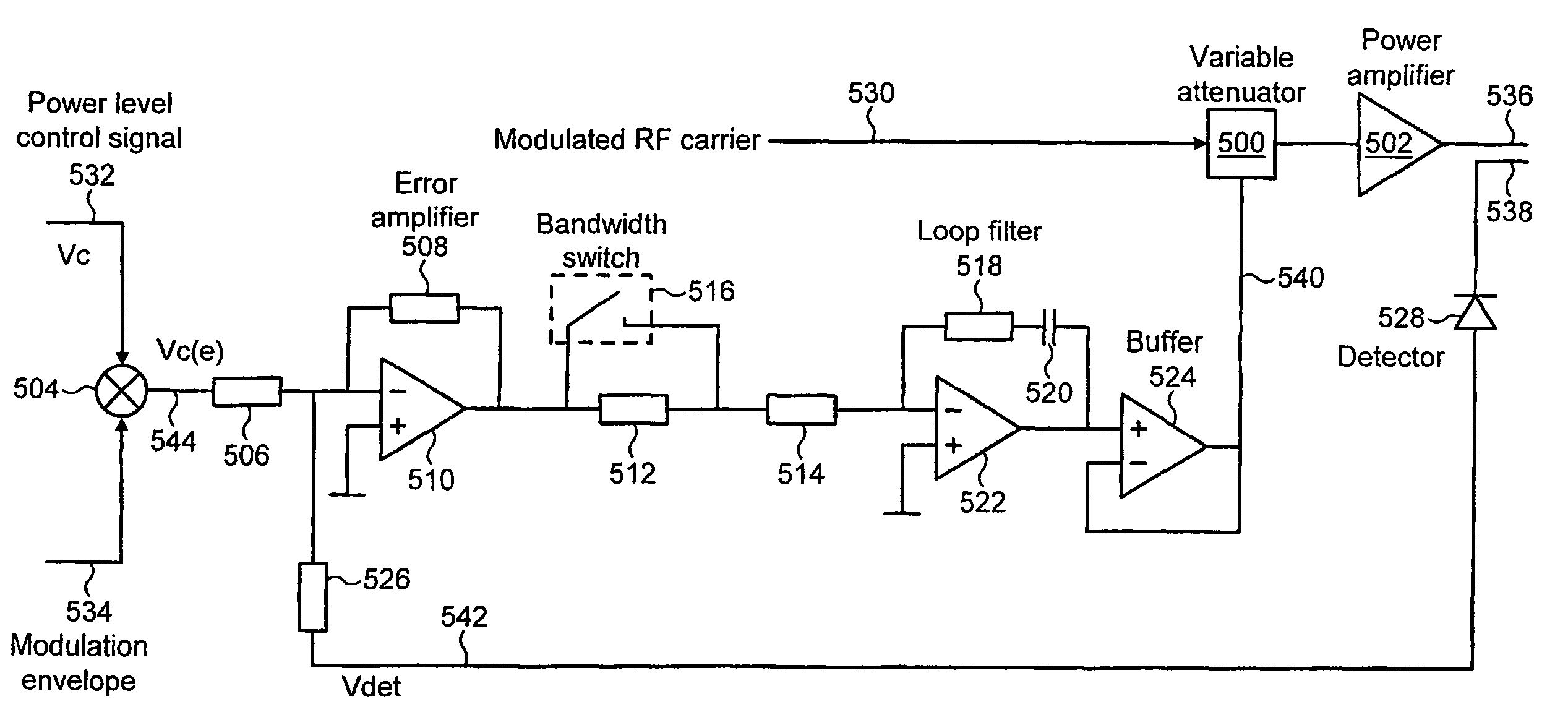
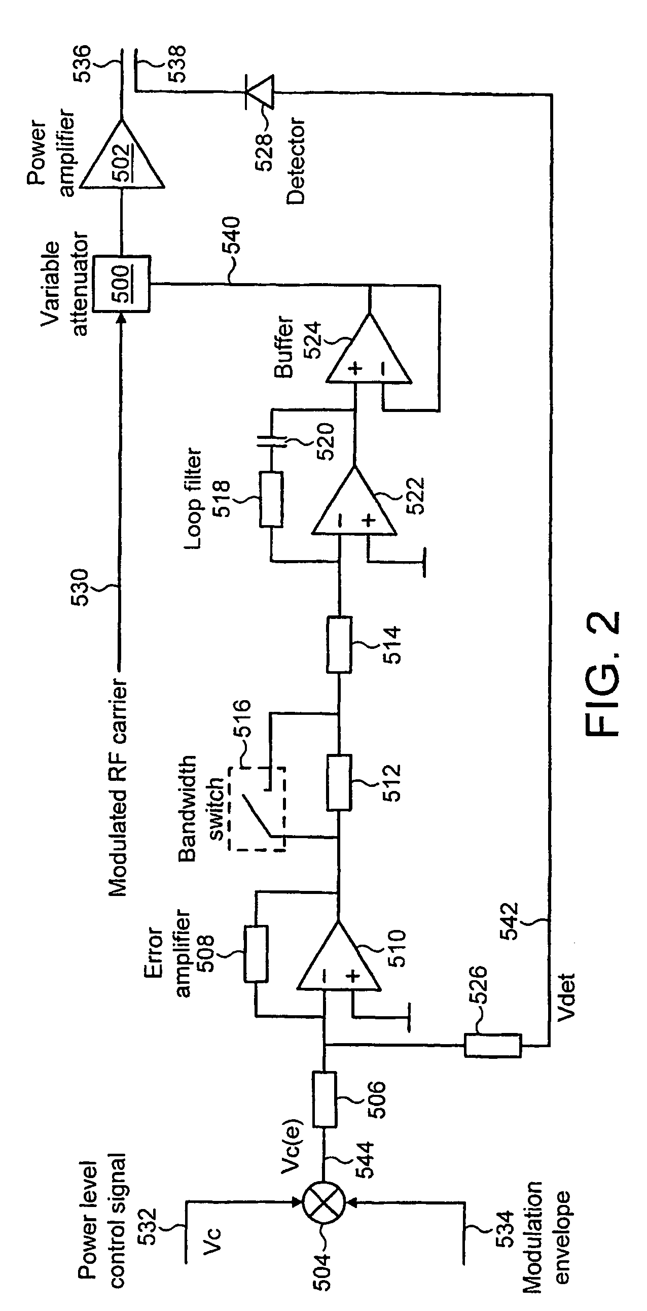
[0021]A preferred embodiment of power control system in accordance with the present invention is shown in FIG. 2. The power control system includes a variable attenuator 500, a power amplifier 502, a detector / lineariser comprising a diode 528, a comparator formed by resistors 506 and 526, a mixer 504, an error amplifier comprising operational amplifier 510 and resistor 508, a bandwidth switch comprising resistor 512 and switch 516, a loop filter comprising operational amplifier 522, resistor 518 and capacitor 520, and a buffer 524.

[0022]The variable attenuator 500 receives as a first input on line 530 a modulated RF carrier signal to be transmitted. As will be described in further detail hereinbelow the variable attenuator receives as a second input an attenuator control signal on line 540. The modulated RF carrier signal, after attenuation in the variable attenuator 500, is applied to the power amplifier 502. An amplified output signal is then generated on line 536.

[0023]The input ...


PUM


Abstract

There is disclosed a method and apparatus for control of a power control loop. The method comprises the steps of: amplifying a non-constant envelope modulation signal to thereby produce an output signal; combining a power level control signal with a signal representing the envelop of modulation; comparing the combined signal to a signal representing the power level of the output signal to thereby produce a comparison signal; and attenuating the amplified signal in dependence on said comparison signal.

Description

FIELD OF THE INVENTION[0001]The present invention relates to a technique for power control in transmitters utilising non-constant envelope modulation techniques, and particularly but not exclusively to such transmitters forming part of a wireless communications system.BACKGROUND TO THE INVENTION[0002]Power control loops, such as provided in wireless communication systems, are typically provided to control and maintain output power at a desired level, and to control transient responses when ramping up or down.[0003]In a TDMA signalling format, a framed structure comprises a number of time slots (or channels). A wireless communications system using TDMA, for example a GSM (global system for mobile telecommunications) system, transmits and receives information over each assigned slot or channel. Each channel of a frame is assigned to a different user with transmission (uplink) information on one frequency band and reception (downlink) information on a separate frequency band communicat...

Claims


Application Information

Patent Timeline
Patent Type & Authority Patents(United States)
IPC IPC(8): H01Q11/12H03G3/30H04B7/005
CPCH03G3/3036H03G3/3047H04W52/52
Inventor MOHSEN, SARACHILAND, TIM
Owner NOKIA SOLUTIONS & NETWORKS OY
Why Eureka
Try Eureka