Spark plug having a specific structure of noble metal tip on ground electrode

a technology of ground electrode and spark plug, which is applied in the manufacture of spark plugs, spark plugs, electrical equipment, etc., can solve the problems of cracking or the like in molten bond formation, and achieve the effect of stable spark discharge and easy concentration of electric field strength

Active Publication Date: 2007-11-06
NGK SPARK PLUG CO LTD
View PDF8 Cites 9 Cited by
  • Summary
  • Abstract
  • Description
  • Claims
  • Application Information

AI Technical Summary

Benefits of technology

[0007]The present invention has been achieved in view of the above-described problem. It is therefore an object of the present invention to provide a method of producing a spark plug in which the reliability of a molten bond can be improved.
[0009]In the case of a diameter of 0.8 mm or less in which a molten bond has a small sectional area, the weld strength is easily reduced. In the case where the protrusion distance of the noble metal tip is 0.5 mm or more, stress due to vibration in the process of forming the tapered faces tends to be easily concentrated in the molten bond. By contrast, when a spark plug is produced by the method of the invention, it is possible to avoid this problem.
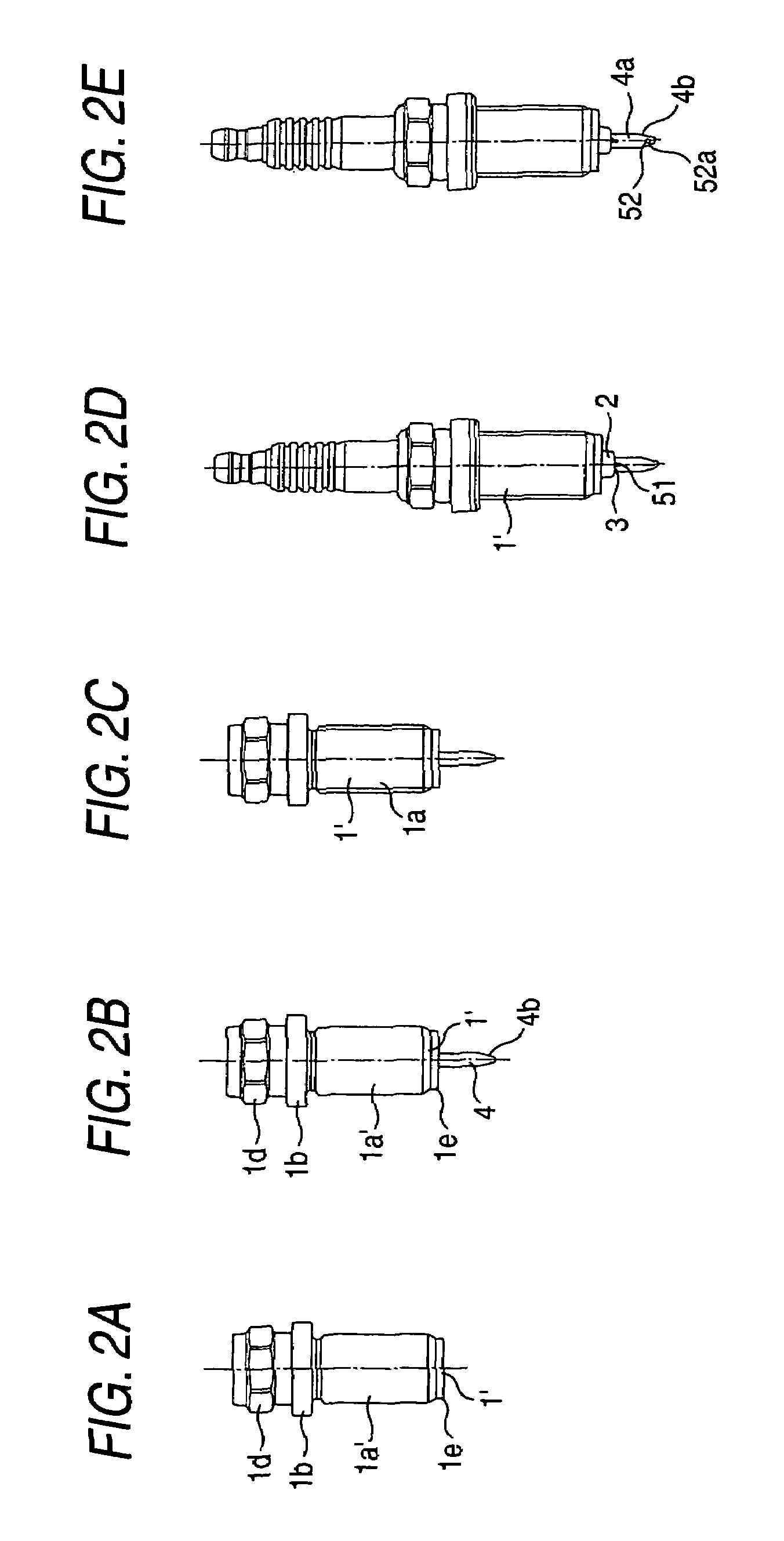
[0012]In order to prevent spark discharge at the molten bond, preferably, the distance between the tip end face of the noble metal tip and the molten bond is increased. Specifically, the height (t) of the unmelted portion of the noble metal tip is set to 0.3 mm or more. In this manner, a spark plug in which the height of the unmelted portion protruding from the molten bond is large tends to be easily broken. This is because of stress concentration due to vibrations in the process of forming the tapered faces. When the laser welding is conducted after the tapered faces are formed, it is possible to avoid stress concentration on the molten bond occurring during formation of the tapered faces.
[0014]Preferably, the molten bond is formed to extend from the inner side face to the tapered faces, and has a curved shape at a corner formed between the inner side face and the tapered faces. When the edges formed at a corner between the inner side face and the tapered faces are angular, the electric field is easily concentrated in these portions. As a result, in such a structure, spark discharge at the molten bond easily occurs, and hence the molten bond is susceptible to damage. By contrast, when the edges formed by the inner side face of the ground electrode and the tapered faces are melted during the laser welding and the molten bond is formed into a curved shape at a corner formed between the inner side face and the tapered faces, damage of the molten bond due to concentration of an electric field can be effectively prevented.
[0016]Since the spark plug has a discharge portion in which the diameter is 0.8 mm or less and the height is 0.5 mm or more, the electric field strength is easily concentrated at the tip end of the discharge portion. Moreover, the molten bond is formed so as to extend from the inner side face to the tapered faces, and a corner formed between the inner side face and the tapered faces has a rounded shape. Therefore, concentration of electric field strength hardly occurs in these portions. Because of a synergistic effect due to these two structural features, the electric field strength is concentrated at the tip end of the discharge portion, and hence stable spark discharge is enabled at a low discharge voltage. The spark plug is formed by laser-welding the noble metal tip after the tapered faces are formed. Therefore, the molten bond is not broken by vibrations in the process of forming the tapered faces.

Problems solved by technology

When the ground electrode is formed into a tapered shape after the noble metal tip is laser welded, impact occurring during formation of the tapered shape may cause a crack or the like in a molten bond formed by the welding.

Method used


Image

  • Spark plug having a specific structure of noble metal tip on ground electrode
  • Spark plug having a specific structure of noble metal tip on ground electrode
  • Spark plug having a specific structure of noble metal tip on ground electrode

Examples


examples

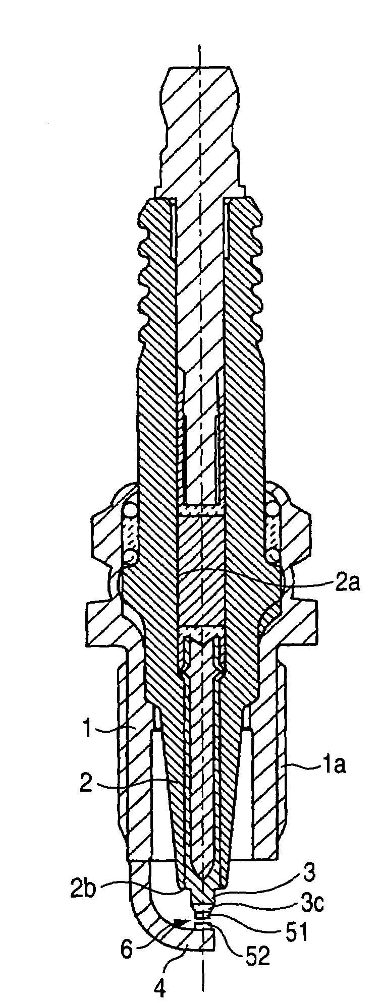
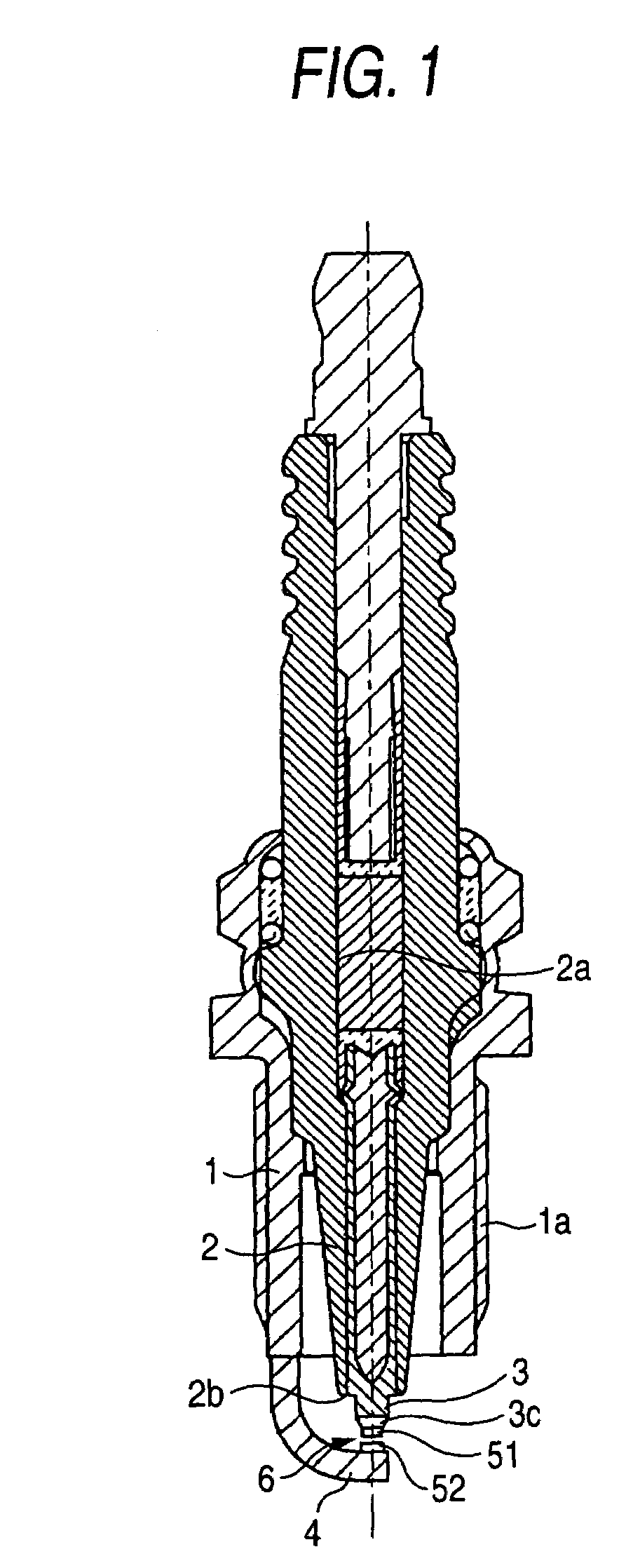
[0046]A preferred arrangement of the discharge portion 52 in the above-described embodiment of the invention will now be described with reference to FIGS. 3 to 5.

[0047]FIG. 3 is a diagram showing positioning of the discharge portion 52 with respect to the inner side face 4a of the ground electrode 4, i.e., the minimum distance L between the tapered faces 4b and the tip end face 4c of the ground electrode 4, and the noble metal tip 52a. FIG. 4 shows test results obtained in evaluating weldability in the case where the minimum distance L is set to have a value of 0 to 1.0 mm. The weldability was evaluated in the following manner. A spark plug was repeatedly subjected to 1,000 cycles in each of which the tip end of the spark plug on the side of the spark discharge gap was heated by a gas burner for two minutes to 1,000° C. in the vicinity of the molten bond between the ground electrode 4 and the noble metal tip 52a, and then air cooled for one minute (corresponding to a travel distance...


PUM


Abstract

A method for producing a spark plug, the spark plug including: a center electrode; an insulator which holds the center electrode therein in a state where a tip end portion of the center electrode protrudes therefrom; a metal shell which holds the insulator therein; a ground electrode which is fixed to the metal shell, the ground electrode having an inner side face having a width that is smaller as it advances toward a tip end side, in a portion of the inner side face positioned between a pair of tapered faces; and a discharge portion which is bonded to the inner side face of the ground electrode by laser welding so as to attain a diameter of 0.8 mm or less and a height of 0.5 mm or more, a discharge gap being formed between the discharge portion and the tip end portion of said center electrode, the method including: forming the tapered faces before the discharge portion is laser-welded to the inner side face.

Description

CROSS REFERENCE TO RELATED APPLICATIONS[0001]This application claims benefit from U.S. Provisional Application No. 60 / 603,270 filed Aug. 23, 2004, incorporated herein by reference.BACKGROUND OF THE INVENTION[0002]1. Field of the Invention[0003]The present invention relates to a method of producing a spark plug, and also to a spark plug.[0004]2. Description of the Related Art[0005]JP-A-2002-237365 discloses in FIG. 26 a ground electrode in which a noble metal tip is laser-welded to an inner side face that is formed into a tapered shape as it advances toward the tip end side, so as to protrude from the inner side face.SUMMARY OF THE INVENTION[0006]When the ground electrode is formed into a tapered shape after the noble metal tip is laser welded, impact occurring during formation of the tapered shape may cause a crack or the like in a molten bond formed by the welding. Particularly, this phenomenon has a high tendency to occur when laser welding is conducted in a state where, in order ...

Claims


Application Information

Patent Timeline
Patent Type & Authority Patents(United States)
IPC IPC(8): H01T13/20H01T13/39H01T21/02
CPCH01T21/02H01T13/39
Inventor SUZUKI, AKIRAMATSUTANI, WATARU
Owner NGK SPARK PLUG CO LTD
Why Eureka
Try Eureka