Circuit for driving flat panel display

a flat panel display and circuit technology, applied in the direction of instruments, static indicating devices, etc., can solve the problems of increasing the thickness of the weight of the display, high radiation, high power consumption, etc., and achieve the effect of improving the response speed or the reaction speed

Active Publication Date: 2007-11-06
AU OPTRONICS CORP
View PDF3 Cites 7 Cited by
  • Summary
  • Abstract
  • Description
  • Claims
  • Application Information

AI Technical Summary

Benefits of technology

[0009]Accordingly, the present invention provides a circuit for driving flat panel display to improve the response speed or the reaction speed.
[0010]According to an embodiment of the present invention, two complementary transistors are adapted for data sampling of storage capacitor in order to reduce feed-through effect to improve current quality. On the other hand, the capacitance of the storage capacitor is reduced so that the flat panel display can be operated at a higher frequency.
[0015]Because the current density flowing through the transistor is controlled by the transmission gate comprised of two complementary transistors, and therefore the feed-through effect is avoided and also a better grayscale performance is achieved via data sampling of the storage capacitor by the transmission gate. Meanwhile, storage capacitor is reduced to achieve higher operation frequency of the pixels. Since storage capacitor is reduced, higher resolution of the current-driven flat panel display is achieved.

Problems solved by technology

Presently, traditional cathode ray tube display (CRT display), is being gradually replaced by a flat display because of its disadvantages of occupying larger space, heavier, high radiation, high power consumption compared to the flat panel displays.
Accordingly, the inclusion of backlight module and the color filters into the LCD display will increase the weight the thickness and the power consumption thereof.
Thus grayscale distortion problem would occur since pixels are of low uniformity.
Accordingly, this approach is not desirable.

Method used


Image

  • Circuit for driving flat panel display
  • Circuit for driving flat panel display
  • Circuit for driving flat panel display

Examples


Embodiment Construction

[0027]This present invention applies to various current-driven flat panel displays. In favor of description for this present invention, an organic luminescence emitting display (OLED) is exemplary. Thus the scope of the present invention is not limited with the following description of the preferred embodiments.

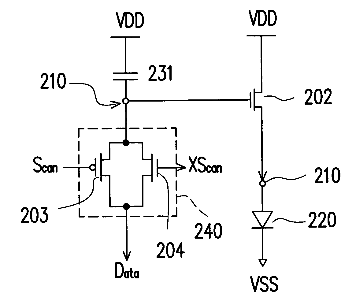
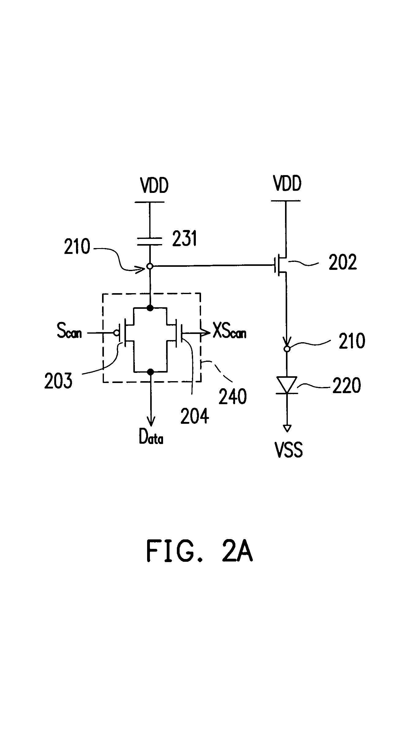
[0028]Referring to FIG. 2A, a block diagram of a circuit for driving a current-driven flat panel display according to one preferred embodiment of the present invention is shown. In FIG. 2A, circuit of one of the pixels of the OLED display is depicted, which illuminates upon receiving the current outputted from current output terminal 210. In this preferred embodiment, the OLED in the figure is an organic luminescence emitting diode, for example. In this embodiment of the present invention, two complementary transistors 203 and 204 are used in order to maintain node a at a voltage Va. The two transistors 203 and 204 are complementary transistors, meaning one being N-type trans...


PUM


Abstract

The present invention provides a circuit for driving a flat panel display, including a storage capacitor, a transmission gate and a current-limiting transistor. A first terminal of the storage capacitor is coupled to a system voltage, and a second terminal of the storage capacitor is at storage voltage. A first input / output terminal of the transmission gate is coupled to the storage voltage, and the second input / output terminal of the transmission gate is coupled to the data current source. A first gate terminal of the transmission gate is coupled to the first signal; a second gate terminal of the transmission gate is coupled to the second signal. A gate terminal of the current-limiting transistor is coupled to the storage voltage, wherein a first source / drain terminal is coupled to the system voltage, and a second source / drain terminal provides current for driving the flat panel display.

Description

CROSS-REFERENCE TO RELATED APPLICATION[0001]This application claims the priority benefit of Taiwan application serial no. 92133975, filed on Dec. 3, 2003.BACKGROUND OF THE INVENTION[0002]1. Field of the Invention[0003]This invention generally relates to a circuit of a flat panel display, and more particularly to a circuit for driving a flat panel display.[0004]2. Description of Related Art[0005]In the present 21st century information era, interface between users and electronic products, namely, display panels, play significant role in our everyday. Presently, traditional cathode ray tube display (CRT display), is being gradually replaced by a flat display because of its disadvantages of occupying larger space, heavier, high radiation, high power consumption compared to the flat panel displays. Accordingly, because the flat panel display is flatter and thinner occupying less space, lighter, consume less power, and provides high quality display, has become the main stream of the next ...

Claims


Application Information

Patent Timeline
Patent Type & Authority Patents(United States)
IPC IPC(8): G09G3/32G09G3/36
CPCG09G3/3233G09G3/3241G09G3/325G09G2300/0809G09G2330/025G09G2300/0861G09G2310/0251G09G2320/0252G09G2300/0842
Inventor SUN, WEIN-TOWN
Owner AU OPTRONICS CORP
Why Eureka
Try Eureka