Active integrated rectifier regulator

Inactive Publication Date: 2007-11-06
ELECTRONICS MOTION SYST HLDG
View PDF18 Cites 30 Cited by
  • Summary
  • Abstract
  • Description
  • Claims
  • Application Information

AI Technical Summary

Benefits of technology

[0009]In the automotive art, most generation systems are underpowered at idle speed, which results in the negative charging of the battery. According to the prese

Problems solved by technology

In the automotive art, most generation systems are underpowered at idle speed, which results in the negative charging of the battery.
A conventional passive diode rectifier ac

Method used


Image

  • Active integrated rectifier regulator
  • Active integrated rectifier regulator
  • Active integrated rectifier regulator

Examples


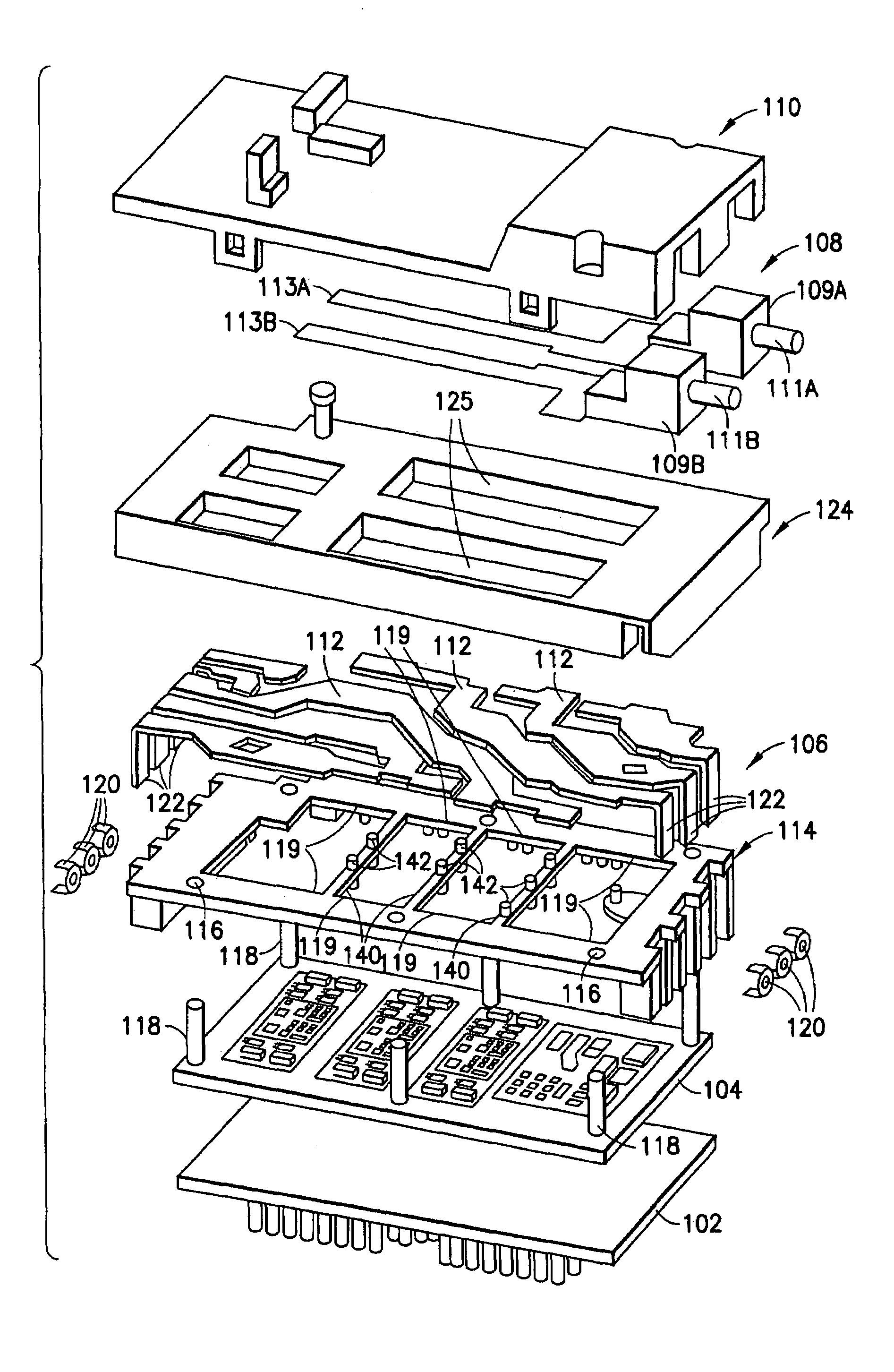
Embodiment Construction

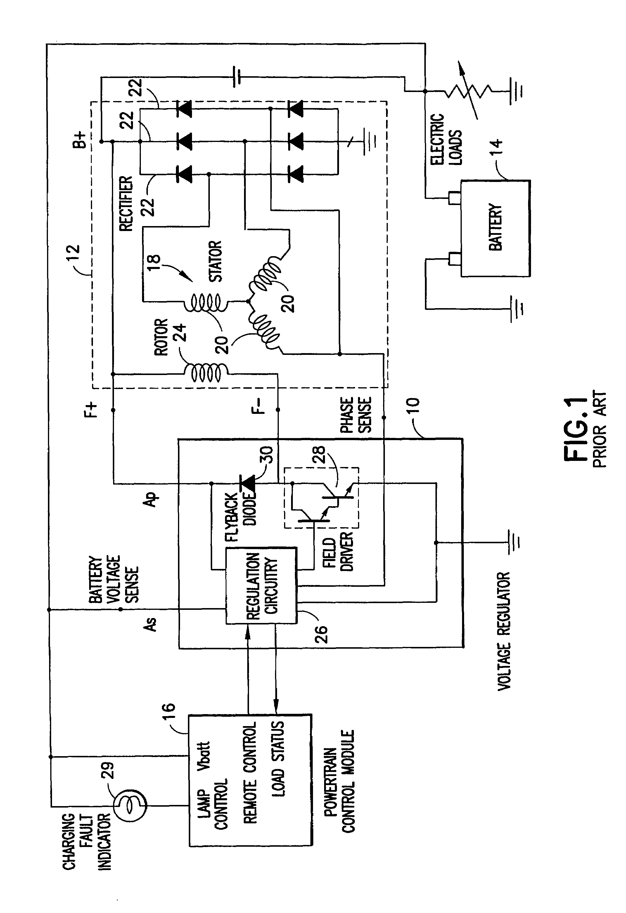
[0052]Referring to FIG. 1, a conventional automotive electrical system includes voltage regulator 10, alternator 12, battery 14, and power train control module (PCM) 16. As is well known, alternator 12 is operatively coupled to the engine to produce an electrical output.

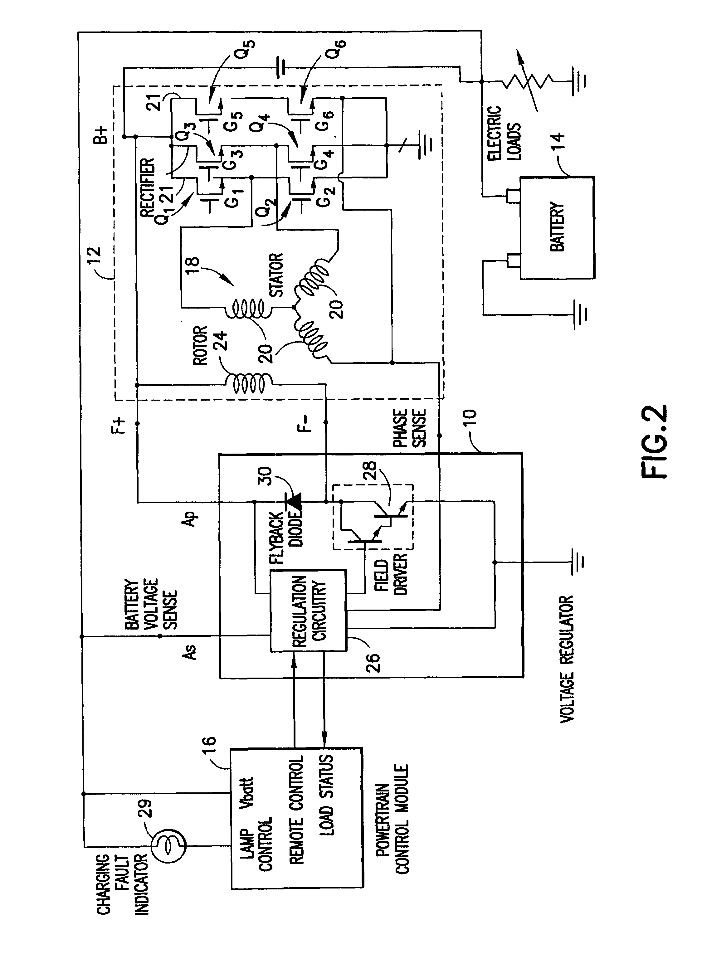
[0053]A conventional alternator 12 includes a three phase stator 18. Stator 18 includes three phases 20. The output from each phase 20 is connected to a respective half wave diode rectifier 22 for rectification. As a result, the alternating current produced by stator 18 is transformed into a DC current. The DC current obtained is then used to, among other functions, charge battery 14.

[0054]Alternator 12 further includes field coil 24. Voltage regulator 10 regulates the current supplied to field coil 24 in order to control the output of stator 18, and, consequently, the output of alternator 12.

[0055]Voltage regulator 10 includes regulation circuit 26, and field driver switch 28. In one known design, regulation circuit...


PUM


Abstract

An active integrated rectifier and regulator module for providing charging current to a battery of an automobile including a stacked structure comprising two lead frames disposed above on another, the module including a voltage regulator and elements for active rectification of alternating current from a stator.

Description

RELATED APPLICATION[0001]The application is based on and claims benefit of U.S. Provisional Application No. 60 / 449,777, filed Feb. 25, 2003, entitled Active Integrated Rectifier Regulator, to which a claim of priority is hereby made.BACKGROUND OF THE INVENTION[0002]In the last decade, the automotive industry has seen a rise in demand for electrical energy especially for light vehicles. This trend is the result of an increase in the amount of electrical comfort and safety features in modem vehicles. Another contributing factor is the increasing electrification of formerly purely mechanical functions as can be seen by all the upcoming x-by-wire systems.[0003]The development in electrical power generation has been struggling to keep up with this demand. However, the entrance barriers associated with new concepts for power generation systems have so far been too high to allow a quick proliferation. Nevertheless, there have been many developments in many research labs of the automotive i...

Claims


Application Information

Patent Timeline
IPC IPC(8): H05K7/20H02H7/06H02J7/24
CPCH02J7/248H02H7/06Y02T90/127H02M7/003H02J7/0042H02J2310/46Y02T90/12
Inventor LINKE, MARIO
Owner ELECTRONICS MOTION SYST HLDG
Why Eureka
Try Eureka