
Control network for vehicle dynamics and ride control systems having distributed electronic control units

a technology of electronic control unit and control network, which is applied in the direction of braking system, braking components, transportation and packaging, etc., can solve the problems of increasing complexity of factors, high number of individual components, and high complexity of design, so as to simplify the resolution of conflicts, reduce the complexity of components, and simplify the design

Inactive Publication Date: 2007-11-13
HALDEX BRAKE PROD LTD
View PDF19 Cites 2 Cited by
  • Summary
  • Abstract
  • Description
  • Claims
  • Application Information

AI Technical Summary

Benefits of technology

"The invention provides an electrical control network for heavy vehicles that offers many advantages such as reduced components, simplified design, unified communication for different types of control systems, and flexibility for upgrading and new systems. The control network includes a central control unit and a distributed electronic control unit that work together to control various vehicle components such as brakes, suspension, and steering. The central control unit receives sensor signals from sensors and generates control signals for the vehicle components. The distributed electronic control unit receives the sensor signals and generates local control signals for controlling only some of the vehicle components. The control network also includes a conflict resolution scheme to resolve conflicts between the central control signals and the local control signals. Overall, the invention simplifies vehicle control and improves performance."

Problems solved by technology

A disadvantage of known systems is their complexity in terms of design, assembly, maintenance, and refurbishment.
Factors increasing complexity include a high number of individual components, using pressurized air for both control information and application force, and conflicts between control strategies.
These disadvantages are exacerbated by the proliferation of different types of control strategies.
For example, inherent conflicts existing between antilock braking, traction, manual inputs / overrides, and other vehicle dynamics schemes can lead to “lost” or cycling braking systems creating a safety hazard.

Method used


Image

  • Control network for vehicle dynamics and ride control systems having distributed electronic control units
  • Control network for vehicle dynamics and ride control systems having distributed electronic control units
  • Control network for vehicle dynamics and ride control systems having distributed electronic control units

Examples


Embodiment Construction

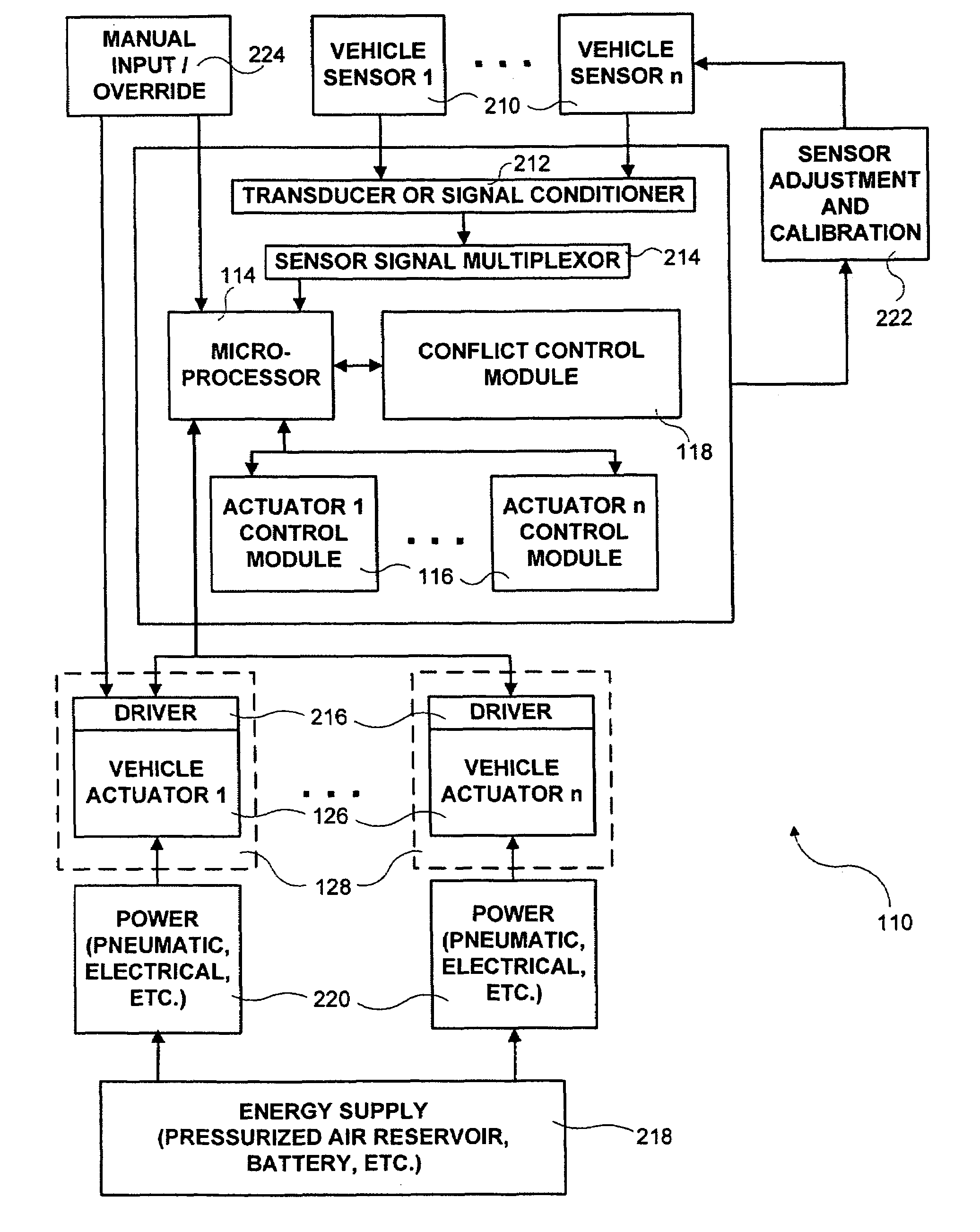
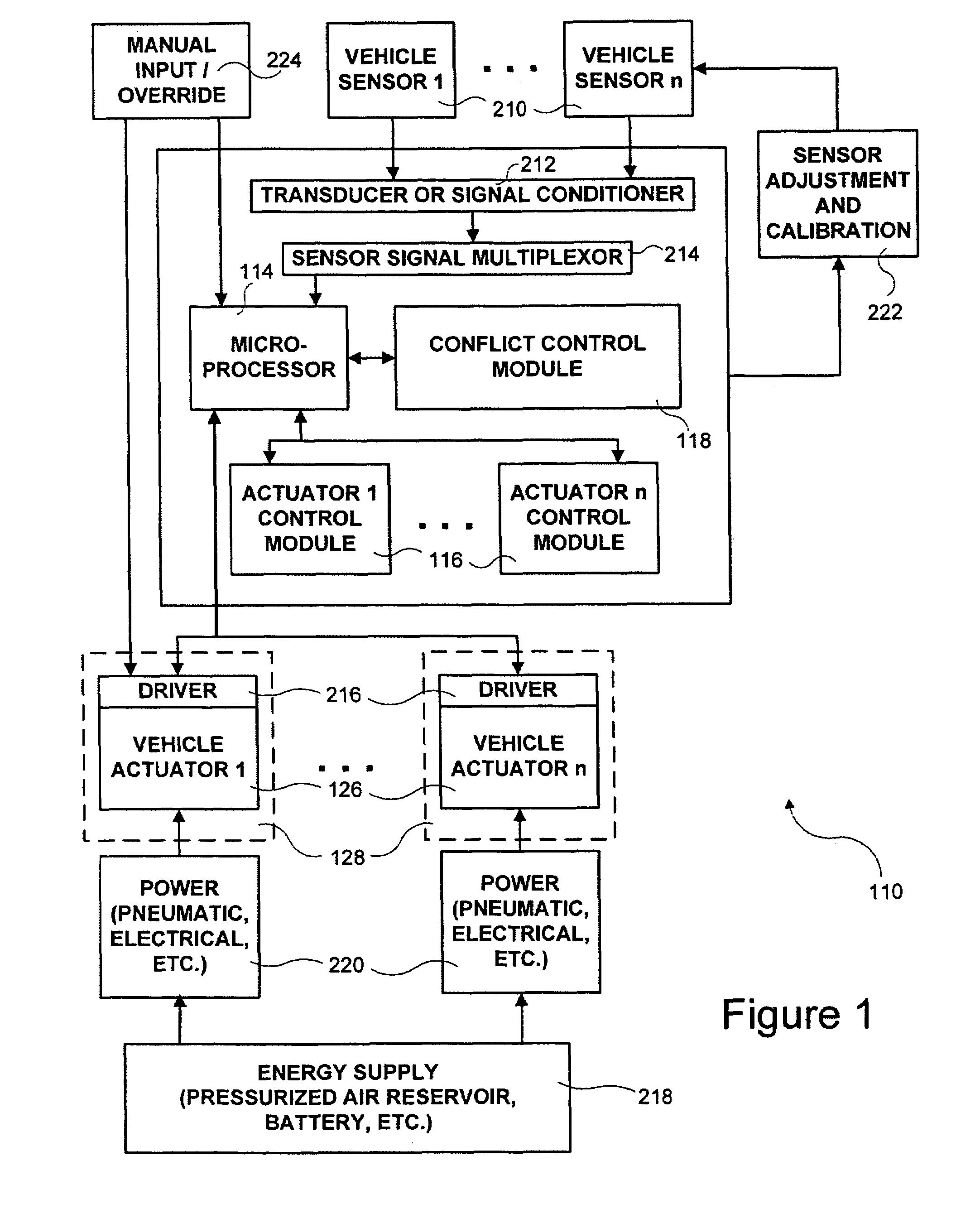
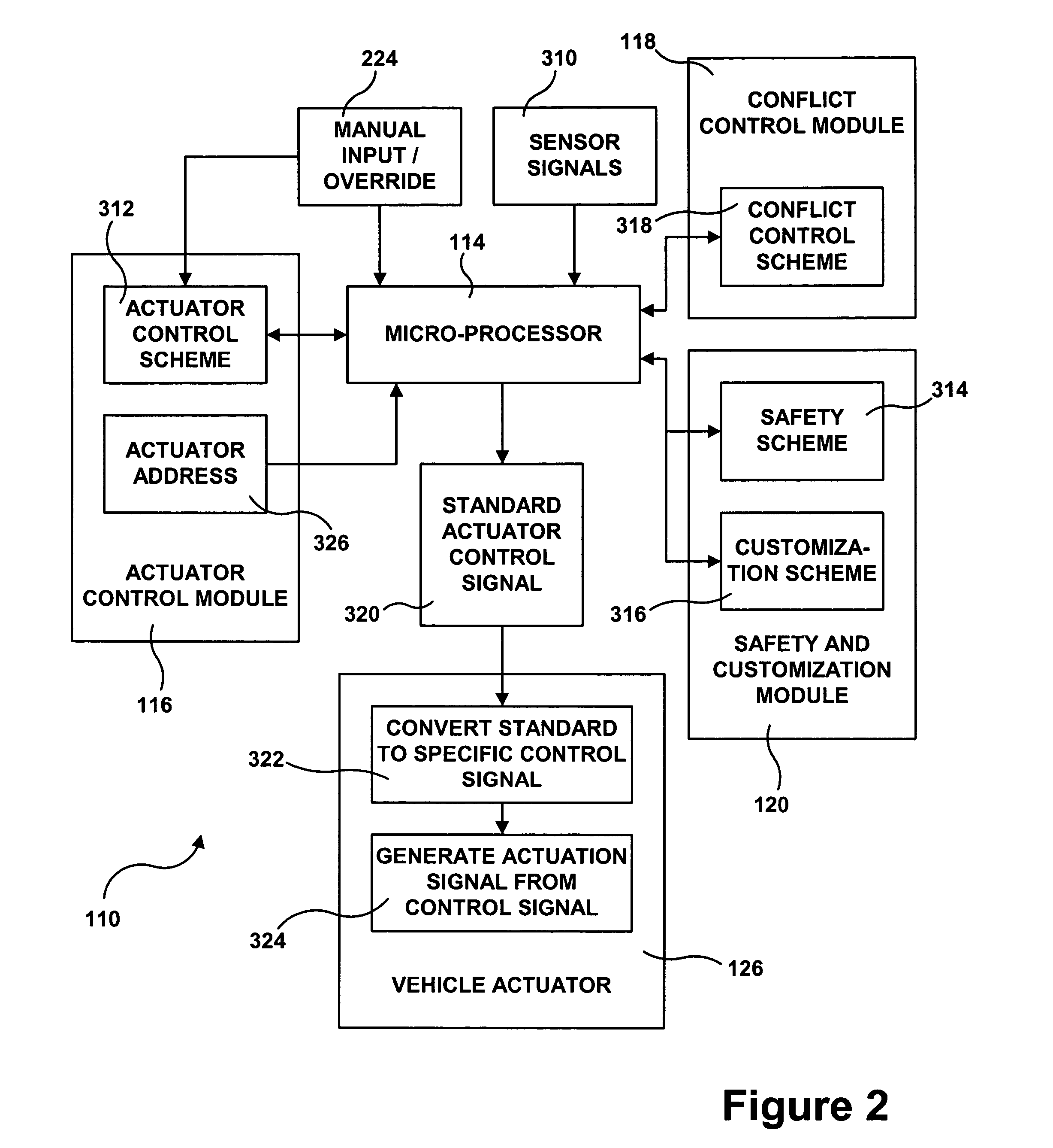
[0036]Referring first to FIGS. 1 and 2, a system 110 for operating vehicle dynamics and ride control systems in heavy vehicles in accordance with certain embodiments of the present invention is schematically shown. What is meant by “vehicle dynamics and ride control systems” is those systems of a vehicle which are responsible for control of the vehicle's movement and its interaction with the road. Examples of such systems include the electronic brake system (EBS), the antilock brake system (ABS), the suspension system, the traction control system, the anti-slip regulation (ASR) system, the steering system, the stability control system, the electronic stability program (ESP), the adaptive cruise control (ACC) system, various components of the diagnostics system, the trailer interface, the transmission, the air management control system, the continuous brake retarder, etc. It should be noted that the term “vehicle dynamics and ride control systems” is intended to not include the power...


PUM


Abstract

An electrical control network is laid over one or more vehicle dynamics control and / or ride control systems of a heavy vehicle, which control network controls actuation of components thereof. The invention offers many advantages including reduction of components, simplified design, unified communication for numerous different types of system components, simplified resolution of conflicts between competing control strategies, expandability to additional vehicle systems, and flexibility to upgrade for new, improved vehicle control schemes.

Description

[0001]This application is a continuation-in-part of U.S. patent application No. 10 / 612,178 filed Jul. 2 2003, which application is currently pending.FIELD OF THE INVENTION[0002]The present invention relates to control networks for vehicle dynamics and ride control systems in heavy vehicles.BACKGROUND OF THE INVENTION[0003]Pneumatic vehicle dynamics control systems and ride control systems, such as brake systems and suspension systems, for heavy vehicles have been known and used for many years. Pressurized air has been used not only as the force to actuate components of such systems but also as the medium to convey control information to various system components.[0004]More recently, control information has been transmitted to heavy vehicle dynamics control and ride control system components by electrical signals. Typically, a single task processor or electrical switch provides control information to a single type of component. The control information is generated according to a sche...

Claims


Application Information

Patent Timeline
Patent Type & Authority Patents(United States)
IPC IPC(8): B60T13/00B60T13/26B60G17/0195B60G17/052B60T8/17B60T13/66B60T13/74B60T17/22
CPCB60G17/0195B60G17/0523B60T8/885B60T17/221B60G2206/011B60G2206/0116B60G2500/02B60T2270/82B60G2600/71B60G2800/85B60T2260/08B60G2500/205
Inventor BALE, PAULPRESCOTT, ROBERT DAVIDNILSSON, PETERLINDQVIST, ANDERS
Owner HALDEX BRAKE PROD LTD
Learn More