
Surface discharge type air cleaning device

a technology of air cleaning device and discharge voltage, which is applied in the direction of heating type, lighting and heating apparatus, separation processes, etc., can solve the problems of reducing the onset voltage and input energy necessary to cause discharge, reducing the number of hydroxyl radicals and negative ions, and reducing the power consumption. , the effect of reducing the onset voltage and input energy

Active Publication Date: 2007-11-13
LG ELECTRONICS INC
View PDF14 Cites 21 Cited by
  • Summary
  • Abstract
  • Description
  • Claims
  • Application Information

AI Technical Summary

Benefits of technology

The present invention provides a surface discharge type air cleaning device with a depressed structure discharge electrode pattern that lowers onset voltage and input energy, resulting in increased generation of hydroxyl radicals and negative ions while decreasing the generation of ozone. This increases sterilization and decomposition of noxious gases, prevents decrease in service life of the device due to partial deterioration of the discharge electrode, reduces power consumption, and improves air cleaning efficiency. The device has a simplified structure and reduced manufacturing costs.

Problems solved by technology

Consequently, power consumption is low, and noise generated from the conventional surface discharge type air cleaning device is small, and therefore, air is efficiently cleaned by the conventional surface discharge type air cleaning device even when the conventional surface discharge type air cleaning device is used in a small space.
As a result, there is a limit in lowering the onset voltage and input energy necessary to cause discharge.
Consequently, the number of hydroxyl radicals and negative ions, which are generated when the voltage is low, is decreased, and the amount of ozone, which is toxic to humans, is increased.
In addition, power consumption is increased.
Also, partial deterioration of the electrode occurs rapidly due to partial increase of thermal stress, and therefore, the service life of the surface discharge type air cleaning device is shortened, and discharge safety is also lowered.
Consequently, the structure of the conventional surface discharge type air cleaning device is complicated, and therefore, manufacturing costs of the conventional surface discharge type air cleaning device are increased.

Method used


Image

  • Surface discharge type air cleaning device
  • Surface discharge type air cleaning device
  • Surface discharge type air cleaning device

Examples


Embodiment Construction

[0039]Now, preferred embodiments of the present invention will be described in detail with reference to the accompanying drawings.

[0040]It should be understood that surface discharge type air cleaning devices according to numerous preferred embodiments of the present invention may be proposed, although only the most preferred embodiments of the present invention will be described hereinafter. Also, the basic structure of the surface discharge type air cleaning device according to the present invention is identical to that of the above-described conventional surface discharge type air cleaning device, and therefore, a detailed description thereof will not be given.

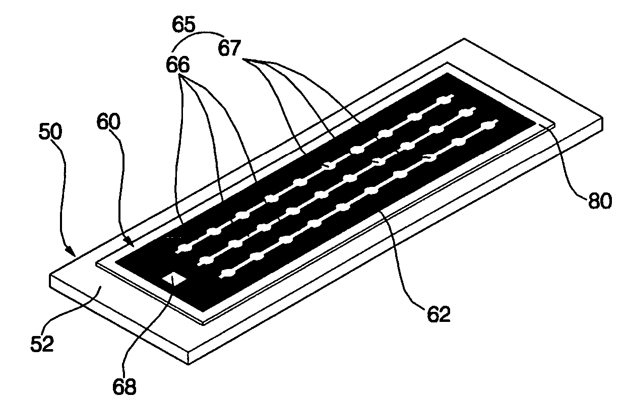
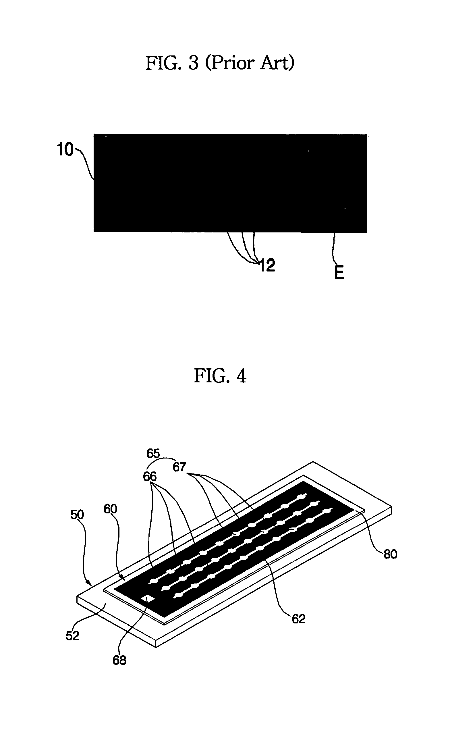
[0041]A surface discharge type air cleaning device 50 according to a first preferred embodiment of the present invention is shown in FIGS. 4 to 6. FIG. 4 is a perspective view of the surface discharge type air cleaning device 50 according to the first preferred embodiment of the present invention showing the upper surface o...


PUM

PropertyMeasurementUnit
insulatingaaaaaaaaaa
shapeaaaaaaaaaa
areaaaaaaaaaaa

Abstract

A surface discharge air cleaning device includes an insulating dielectric body, a discharge electrode formed at the upper surface of the insulating dielectric body, and a ground electrode formed at the lower surface of the insulating dielectric body, the discharge electrode being formed of a closed pattern and at least one non-pattern part, at which the electrode is not formed being disposed in the closed pattern, therefore a uniform and stable plasma formation is accomplished, and the number of hydroxyl radicals and negative ions is increased while the amount of ozone is decreased.

Description

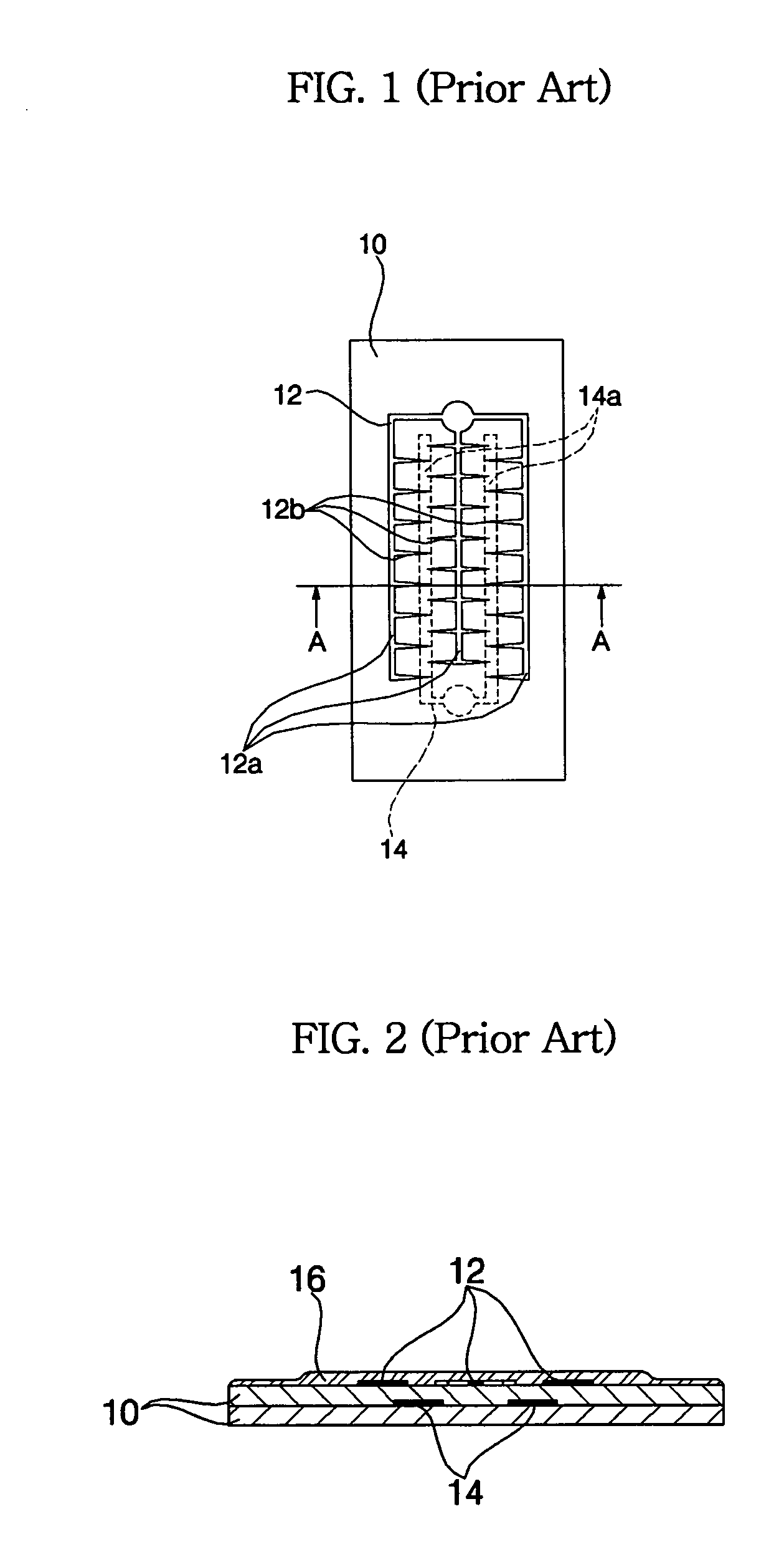
BACKGROUND OF THE INVENTION[0001]1. Field of the Invention[0002]The present invention relates to a surface discharge type air cleaning device mounted in an air conditioner for cleaning air, and, more particularly, to a surface discharge type air cleaning device that is capable of increasing generation of negative ions and hydroxyl (OH) radicals while decreasing generation of ozone, which is toxic to humans, thereby improving noxious gas sterilizing efficiency and air cleaning efficiency.[0003]2. Description of the Related Art[0004]Generally, a surface discharge type air cleaning device adopts a surface discharge plasma chemical processing method. Specifically, the surface discharge type air cleaning device is a ceramic-based high frequency discharge type air cleaning device that is capable of generating a large number of hydroxyl radicals and a large amount of ozone through the formation of a strong plasma area on the surface of an element and processing noxious gases through the us...

Claims


Application Information

Patent Timeline
Patent Type & Authority Patents(United States)
IPC IPC(8): B03C3/40F24F1/0083
CPCB01D53/32B03C3/41B03C3/47B03C3/60F24F3/166H01T23/00F24F1/0007B03C2201/10F24F2003/1635Y02A50/20F24F8/194F24F8/192F24F1/0083B01D46/00B01D46/42B01D53/34
Inventor KIM, HO JUNGCHOI, IN HOYUM, KWAN HOCHOI, HO SEON
Owner LG ELECTRONICS INC
Learn More