Bottle-shaped synthetic resin container

a synthetic resin and container technology, applied in the direction of packaging, lining/internal coating, coating, etc., can solve the problems of reducing the self-standing stability of the container, affecting the contractive deformation of the container, and deteriorating appearance, so as to reduce the buckling strength, facilitate manufacturing control, and simple shape

Active Publication Date: 2007-11-20
YOSHINO KOGYOSHO CO LTD
View PDF13 Cites 28 Cited by
  • Summary
  • Abstract
  • Description
  • Claims
  • Application Information

AI Technical Summary

Benefits of technology

[0009]With the above-mentioned structure according to the present invention, although the circumferential groove has a simple shape that can be realized by a relatively easy manufacturing control, it is yet possible to fully utilize the circumferential groove, upon the internal pressure reduction due to a cooling after hot filling, etc., so as to cause a smooth contractive deformation of the container in its center axis direction. Moreover, even when the contractive deformation proceeds considerably, there is established a state wherein the upper and lower edges of the circumferential groove are brought into contact with each other so as to prevent a further lowering of the buckling strength from such a state, thereby making it possible to suppress an elliptical deformation of the body portion, to preserve a required buckling strength, and to improve the pressure reduction resistance.

Problems solved by technology

As such, the appearance tends to deteriorate due to the deformation of the body portion into elliptical shape upon internal pressure reduction of the container, besides that the self-standing stability of the container tends to be lowered as a result of deformation of the container.
However, in this instance, the corners of the polygon formed by relatively narrow groove bottom portions function as beams, which not only impede the contractive deformation of the container in the longitudinal direction of the bottle by utilizing the groove portions, but also require a relatively strict manufacturing control upon blow molding or the like.

Method used


Image

  • Bottle-shaped synthetic resin container
  • Bottle-shaped synthetic resin container
  • Bottle-shaped synthetic resin container

Examples


Embodiment Construction

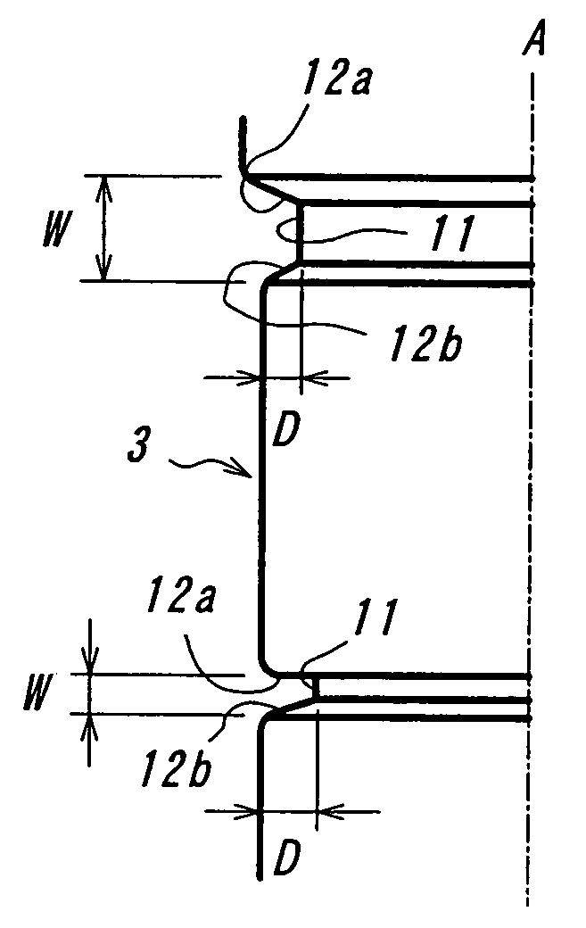
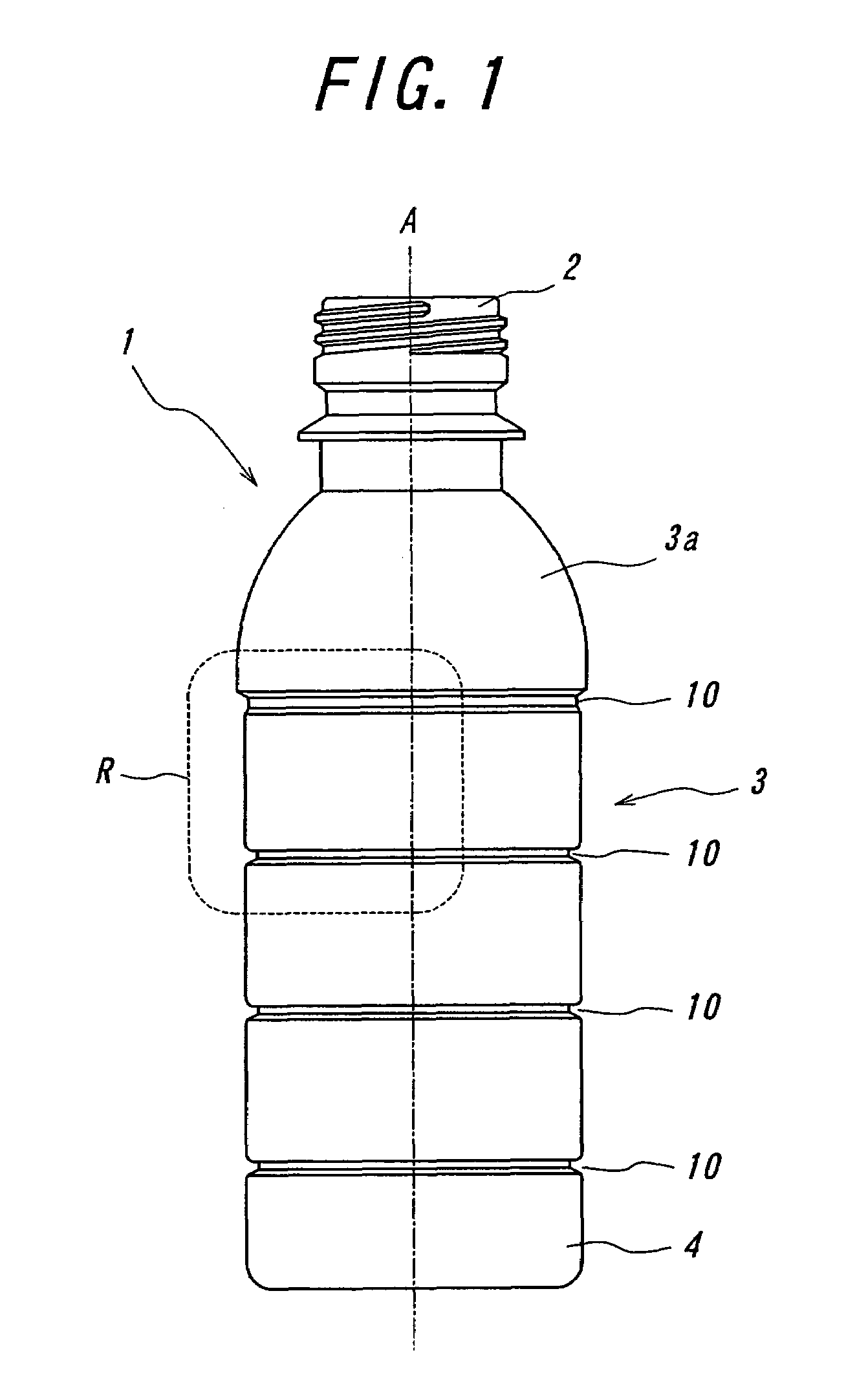
[0018]Referring to FIG. 1, there is shown one embodiment of the present invention that is directed to a bottle-shaped container made of polyethylene-terephthalate (“PET bottle”), and denoted as a whole by reference numeral 1. The PET bottle 1 includes a mouth portion 2, a body portion 3 and a bottom portion 4, which are arranged in the stated sequence, and can be maintained in a self-supporting state with its bottom portion 4 placed on a supporting surface, not shown. The body portion 3 has a shoulder portion 3a at its junction with the mouth portion 2, and is formed with four circumferential grooves 10 extending along the outer surface of the body portion 3 in its circumferential direction. In the illustrated embodiment, these circumferential grooves 10 are arranged in planes perpendicularly intersecting the center axis A of the bottle 1 or the body portion 3. The body portion 3 as a whole has a substantially cylindrical body wall.

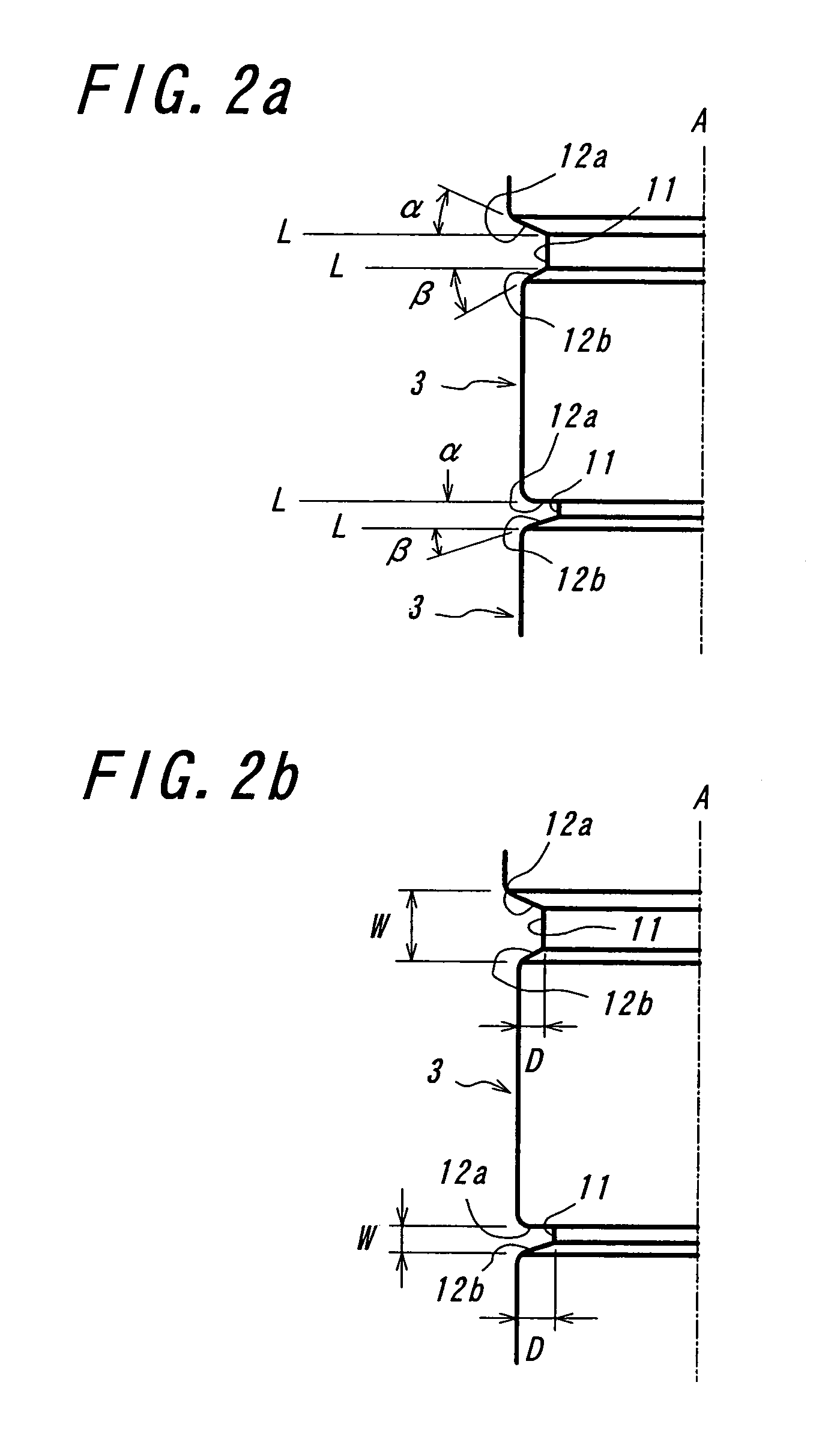
[0019]In the illustrated embodiment, as particularl...


PUM

PropertyMeasurementUnit
angleaaaaaaaaaa
angleaaaaaaaaaa
anglesaaaaaaaaaa

Abstract

A bottle-shaped synthetic resin container (1) includes a body portion (3), and a circumferential groove (10) extending along an outer surface of the body portion (3). The circumferential groove (10) is defined by a groove bottom wall (11) and groove side walls (12a, 12b) extending from the groove bottom (11) to the outer surface of the body portion (3). At least one of the groove side walls (12a, 12b) extends substantially linearly, as seen in a longitudinal-sectional plane including a center axis (A) of the body portion (3), and forms an angle (α, β) of not more than 20° relative to a reference line (L) perpendicular to the center axis (A) of the body portion (3) in the longitudinal-sectional plane of the container (1).

Description

BACKGROUND ART[0001]1. Technical Field[0002]The present invention relates to a bottle-shaped synthetic resin container having a circumferential groove extending along the surface of the container body portion.[0003]2. Prior Art[0004]Generally, bottle-shaped container comprised of a synthetic resin such as polyethyleneterephthalate (“PET”) has a reduced thickness of the body portion. As such, the appearance tends to deteriorate due to the deformation of the body portion into elliptical shape upon internal pressure reduction of the container, besides that the self-standing stability of the container tends to be lowered as a result of deformation of the container. In these respects, as compared to bottle-shaped containers made of glass, aluminum or the like, bottle-shaped synthetic resin container still has a room for further improvement in terms of its applicability to a filling line wherein the containers are transferred by gliding them along the bottom surface, or to an automatic ve...

Claims


Application Information

Patent Timeline
Patent Type & Authority Patents(United States)
IPC IPC(8): B65D1/42B65D1/02B65D23/02B65D1/44
CPCB65D1/0223Y10S215/90B65D2501/0036B65D1/02B65D1/14B65D1/16B65D1/40
Inventor OZAWA, TOMOYUKIIIZUKA, TAKAOTANABE, SHOJI
Owner YOSHINO KOGYOSHO CO LTD
Why Eureka
Try Eureka