Turbine airfoil with counter-flow serpentine channels

a technology of serpentine channels and turbine airfoils, which is applied in the direction of engine fuction, machine/engine, engine manufacturing, etc., can solve the problems of reducing the mechanical life cycle of airfoils, reducing the amount of cooling fluid required, and the likelihood of failure, so as to reduce the required pressure of cooling fluids, reduce the amount of cooling fluid required, and optimize heat exchange

Inactive Publication Date: 2007-11-20
SIEMENS ENERGY INC
View PDF17 Cites 22 Cited by
  • Summary
  • Abstract
  • Description
  • Claims
  • Application Information

AI Technical Summary

Benefits of technology

[0006]This invention is directed to a turbine airfoil having a cooling system in inner aspects of the turbine airfoil for use in turbine engines. The cooling system may be used in any turbine blade. The cooling system may include a pressure side serpentine cooling channel nested with a suction side serpentine cooling channel and positioned within a mid-chord region of the airfoil. Nesting the pressure side serpentine cooling channel within the suction side serpentine cooling channel optimizes heat exchange between the cooling fluids and the materials forming the airfoil to reduce the amount of cooling fluids required, to reduce the required pressure of the cooling fluids, and to provide other benefits.
[0014]An advantage of this invention is that the pressure side serpentine cooling channel is tailored to account for the high temperatures encountered by the pressure side of the airfoil. By initiating the pressure side serpentine cooling channel proximate to the leading edge cooling channel, the pressure of cooling fluid supply may be reduced, which results in an overall reduction in cooling fluid leakage flow in the system.
[0016]Yet another advantage is that having four independent cooling channels creates flexibility in the system to be adapted for different uses in the future.
[0017]Another advantage of this invention is that the separation of the pressure side and suction side serpentine cooling channels eliminates conventional mid-chord cooling fluid flow mal-distribution due to film cooling flow mal-distribution, film cooling hole size, mainstream cooling fluid pressure variation, back-flow margin (BFM), and high blowing ratio for the blade suction side film cooling holes.
[0018]Still another advantage of this invention is that the pressure side and suction side serpentine cooling channels eliminate the pressure differential that typically occurs in conventional cooling channel configurations between pressure and suction sides in a single channel.
[0019]Another advantage of this invention is that the counter-flow of cooling fluid between the pressure side and suction side serpentine cooling channels yields a more uniform temperature distribution for the airfoil mid-chord section.

Problems solved by technology

In addition, turbine vanes and blades often contain cooling systems for prolonging the life of the vanes and blades and reducing the likelihood of failure as a result of excessive temperatures.
The walls forming the pressurized mid-chord cooling channel often remain at temperatures much lower than other portions of the airfoil in contact with hot combustion gases, thereby resulting in a large thermal gradient between these regions.
The large thermal gradient often results in a reduced mechanical life cycle of airfoil components and poor thermal mechanical fatigue (TMF).
Therefore, the inner cooling channel often negatively affects the life cycle of the airfoil.
In order to meet back flow margin criteria, a high cooling supply pressure is needed for this particular design, which results in a large leakage flow of cooling fluids.
This results in over-pressurizing the suction side film cooling holes, which results in tremendous cooling system inefficiencies.

Method used


Image

  • Turbine airfoil with counter-flow serpentine channels
  • Turbine airfoil with counter-flow serpentine channels
  • Turbine airfoil with counter-flow serpentine channels

Examples


Embodiment Construction

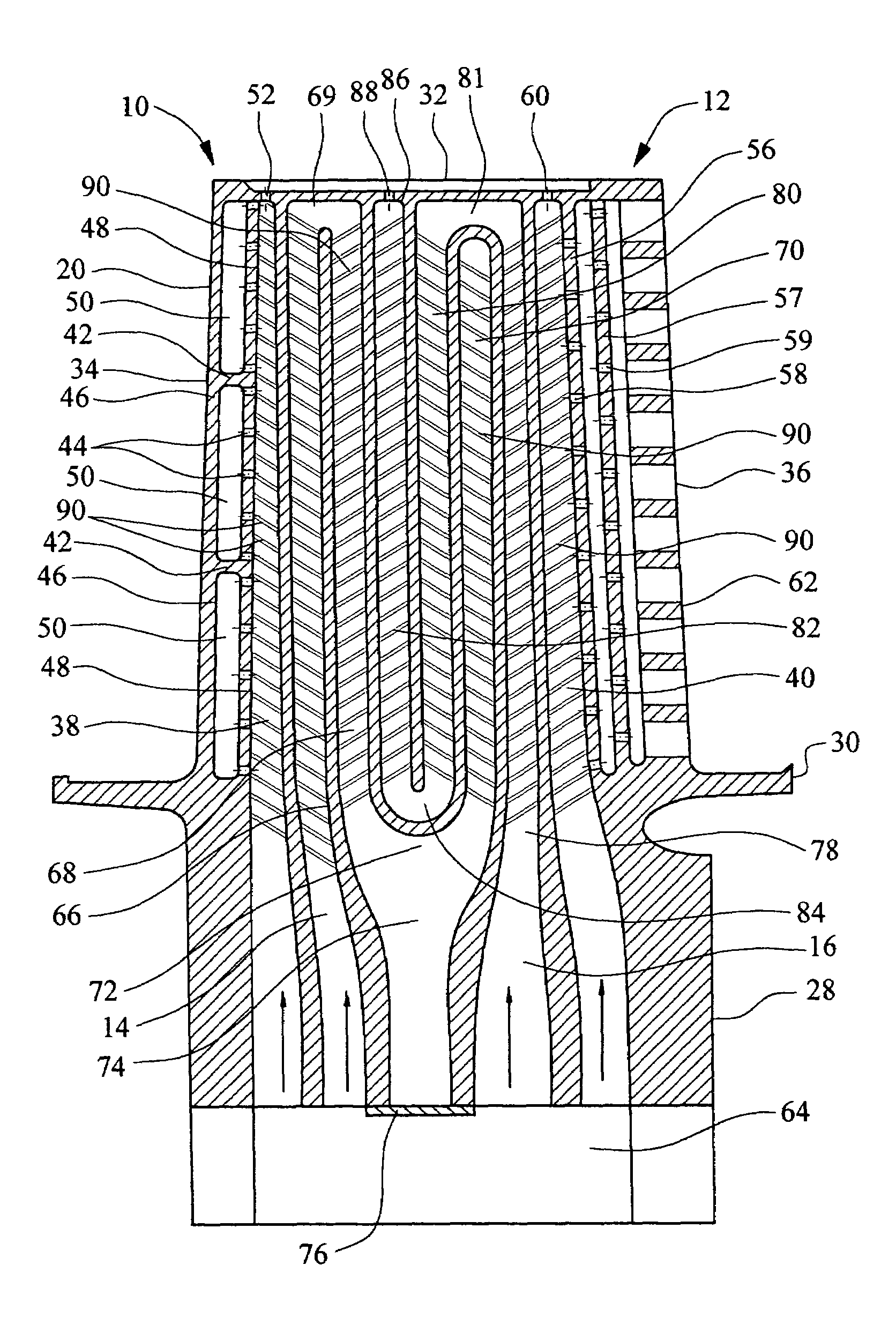
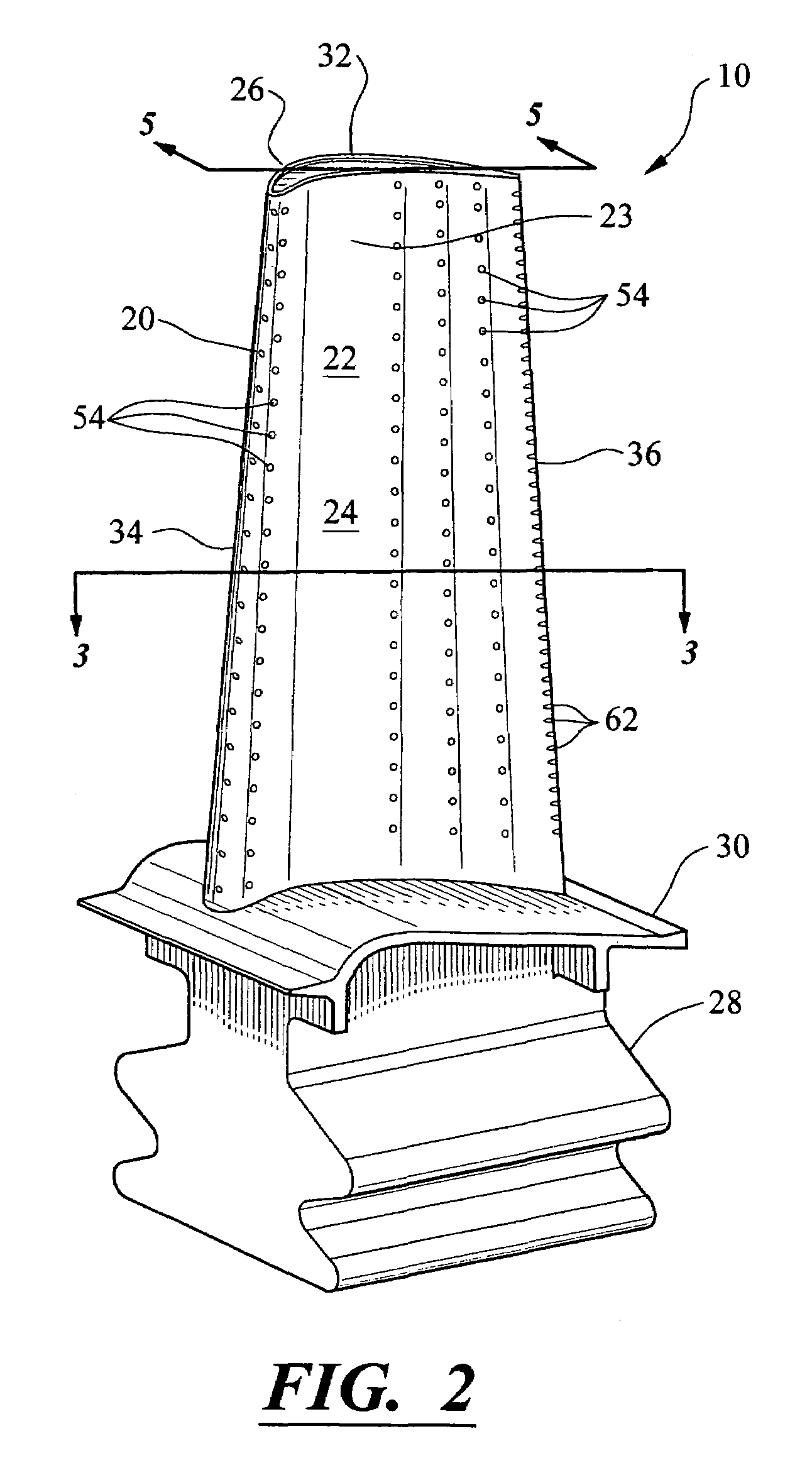
[0028]As shown in FIGS. 2-6, this invention is directed to a turbine airfoil 10 having a cooling system 12 in inner aspects of the turbine airfoil 10 for use in turbine engines. The cooling system 12 may be used in any turbine blade. The cooling system 12 may include a suction side serpentine cooling channel 16 nested within a pressure side serpentine cooling channel 14 and positioned within a mid-chord region 18 of the airfoil 10. Nesting the pressure side serpentine cooling channel 14 within the suction side serpentine cooling channel 16 optimizes heat exchange between the cooling fluids and the materials forming the airfoil 10, reduces the amount of cooling fluids required, reduces the required pressure of the cooling fluids, and provides other benefits.

[0029]As shown in FIG. 2, the turbine airfoil 10 may be formed from a generally elongated airfoil 20 having an outer surface 22 adapted for use, for example, in an axial flow turbine engine. Outer surface 22 of the outer wall 23 m...


PUM


Abstract

A turbine airfoil usable in a turbine engine and having at least one cooling system. The cooling system may include a pressure side serpentine cooling channel and a suction side serpentine cooling channel. The cooling channels may be nested within each other to optimize heat exchange between the cooling fluids and the materials forming the airfoil, to reduce the amount of cooling fluids required, to reduce the required pressure of the cooling fluids, and to provide other benefits. The pressure side serpentine cooling channel may pass cooling fluids chordwise towards the trailing edge, and the suction side serpentine cooling channel may pass cooling fluids chordwise towards the leading edge.

Description

FIELD OF THE INVENTION[0001]This invention is directed generally to turbine airfoils, and more particularly to hollow turbine airfoils having cooling channels for passing fluids, such as air, to cool the airfoils.BACKGROUND[0002]Typically, gas turbine engines include a compressor for compressing air, a combustor for mixing the compressed air with fuel and igniting the mixture, and a turbine blade assembly for producing power. Combustors often operate at high temperatures that may exceed 2,500 degrees Fahrenheit. Typical turbine combustor configurations expose turbine vane and blade assemblies to these high temperatures. As a result, turbine vanes and blades must be made of materials capable of withstanding such high temperatures. In addition, turbine vanes and blades often contain cooling systems for prolonging the life of the vanes and blades and reducing the likelihood of failure as a result of excessive temperatures.[0003]Typically, turbine airfoils are formed from an elongated p...

Claims


Application Information

Patent Timeline
Patent Type & Authority Patents(United States)
IPC IPC(8): F01D5/18
CPCF01D5/187F05D2250/185F05D2260/2212F05D2260/201F05D2250/182
Inventor LIANG, GEORGE
Owner SIEMENS ENERGY INC
Why Eureka
Try Eureka