Absorbent member and a method of producing an absorbent member

a technology of absorbent members and absorbent parts, which is applied in the field of absorbent members, can solve the problems of inability to exhibit absorption capability, difficult to monitor the position of scattering patterns on the production line, and high cost of performan

Inactive Publication Date: 2007-11-20
KAO CORP
View PDF19 Cites 15 Cited by
  • Summary
  • Abstract
  • Description
  • Claims
  • Application Information

AI Technical Summary

Benefits of technology

[0025]The present invention relates to an efficient and economical method for producing an absorbent member having excellent absorbing performance (absorbency) which is designed to have an increased absorption capacity in a part and to allow that part to fully exhibit its absorbency.
[0026]The present invention also relates to an absorbent member and an absorbent article containing the same, the absorbent member being designed to have an increased absorption capacity in a part and to allow that part to fully exhibit its absorbency and, when used in an absorbent article, giving little uncomfortable feeling to a wearer.
[0027]The present invention also relates to a method of accurately determining the content of fiber and / or the content of an absorbent polymer in a mixture comprising cellulosic fiber and a polyacrylic acid-based absorbent polymer.

Problems solved by technology

Additionally, it is difficult to monitor the position of the scattering pattern on the production line.
Sometimes there are cases in which the polymer particles fall off from the polymer-rich portion, or the polymer particles can cause gel blocking while in use, failing to exhibit absorption capability as expected.
Both absorbent members (a) and (b) require complicated equipment for production and are therefore costly for performance.
Moreover, the polymer of the upper ply can cause gel blocking upon absorption and swelling, which may hinder smooth migration of the absorbed liquid to the lower ply.
Gel blocking can also cause leaks.
Furthermore, these absorbent members with a two-ply structure only in the front portion unavoidably have a difference in stiffness between the two-plied front portion and the single-plied rear portion, which can give a wearer discomfort.
Besides, there is a possibility that the absorbent member thus produced becomes out of shape because of this level difference while the absorbent member is conveyed.
However, conventional methods of quantitative determination have such disadvantages as low accuracy and a complicated operation.
However, it is difficult to choose a sieve of proper mesh size unless the particle size of the absorbent polymer and the fiber length of the pulp fiber are known.
Even though a proper sieve is selected, time-consuming and laborious procedures, such as condition setting, have to be taken so as to minimize scatter of measured values, and measurement must be repeated for accuracy.

Method used


Image

  • Absorbent member and a method of producing an absorbent member
  • Absorbent member and a method of producing an absorbent member
  • Absorbent member and a method of producing an absorbent member

Examples


example 1

(1) Preparation of Absorbent Member

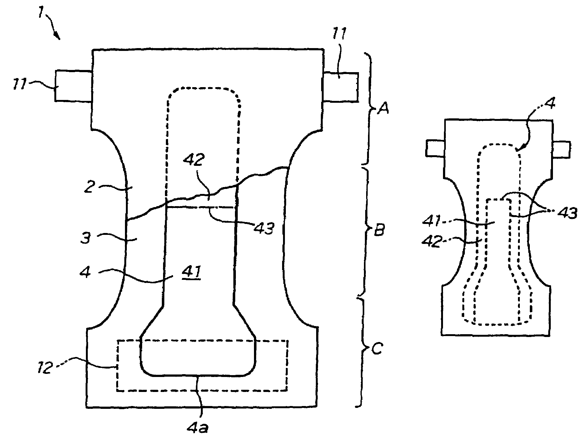
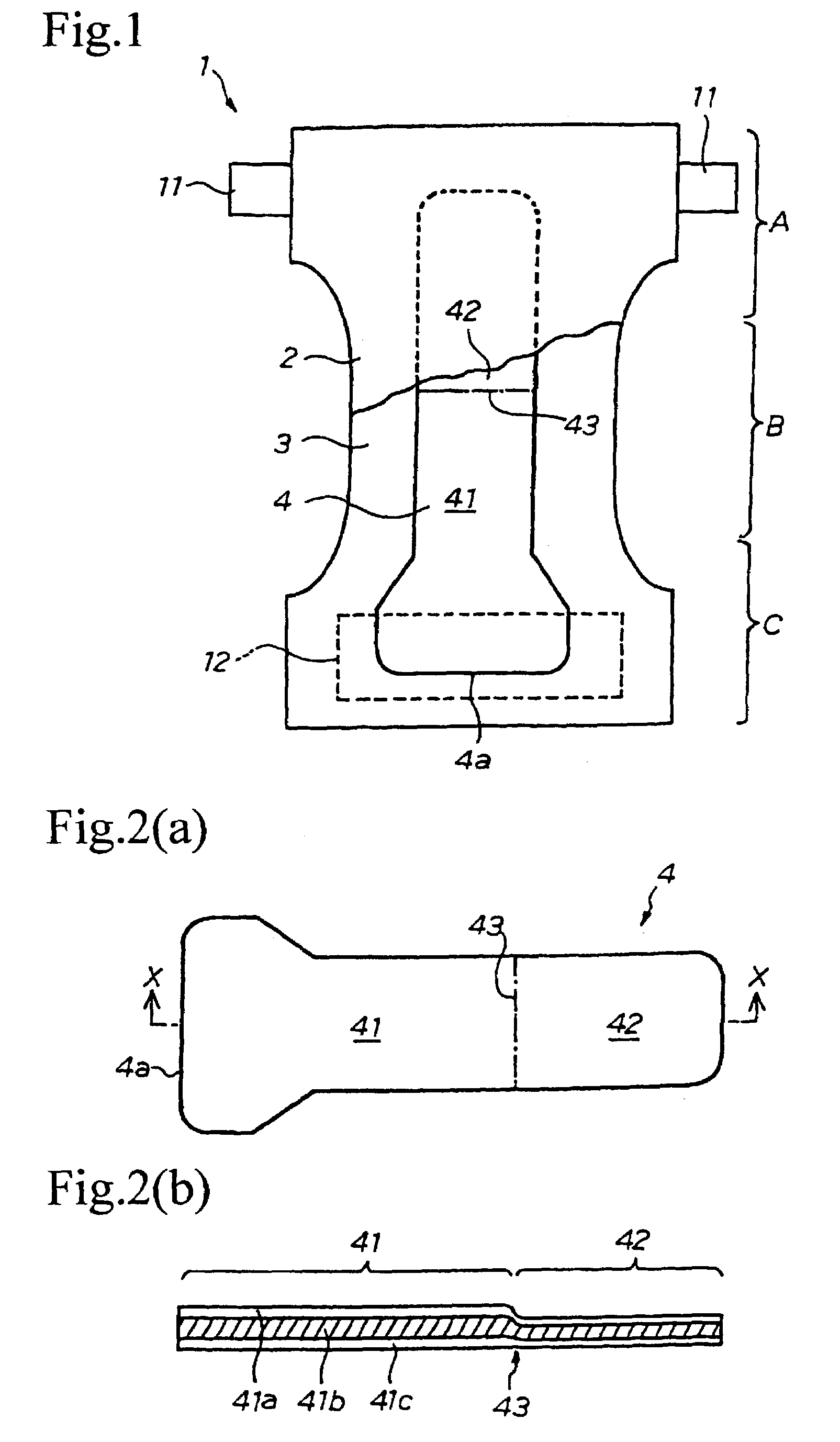
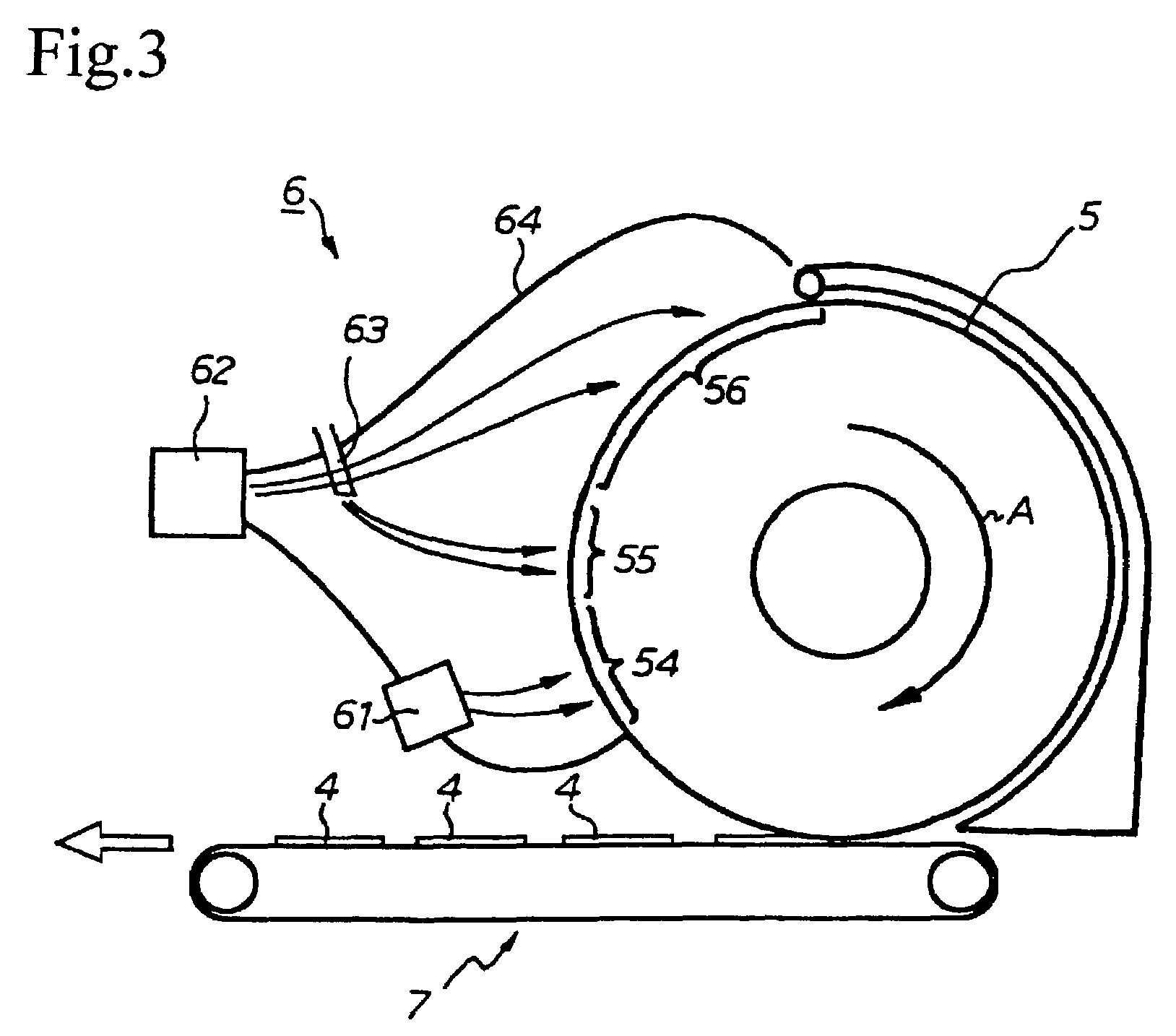
[0103]Absorbent members having the structure shown in FIGS. 2(a) and 2(b) were produced from a superabsorbent polymer and pulp fiber using an apparatus having the configuration shown in FIG. 3.

[0104]The shape of forming recesses and arrangement of first and second suction regions in each recess were as shown in FIG. 4(a). The open area ratio of the first suction region 51 and that of the second suction region 52 were 56% and 5%, respectively. The diameters of suction holes provided in both the first and second suction regions all fell within a range of 0.1 to 0.3 mm and averaged 0.2 mm in both regions. Each chamber provided behind the regions 54 to 56 of the drum 5 was maintained at a vacuum pressure lower than atmospheric pressure by 8 to 11 kPa, and this vacuum pressure was exerted to the first and second suction regions 51 and 52.

[0105]The area, etc. of the first and second suction regions are shown in Table 1, in which “front” and “rear” corres...

examples 2 and 3

[0106]Absorbent members were produced in the same manner as in Example 1, except for changing the open area ratio of the second suction region 52 to 10% (Example 2) or 18% (Example 3).

example 4

[0109]Absorbent members were produced in the same manner as in Example 1, except for changing the arrangement of the first and second suction regions as illustrated in FIG. 5. In Table 1, “T” and “Y” correspond to the first and the second suction regions, respectively.

(2) Absorbent Member

[0110]The absorbent members obtained in Examples 1 to 4 and Comparative Examples 1 and 2 were measured for the pulp and the polymer contents in each of the portion corresponding to the first suction region (i.e., the high basis weight portion 41, represented by “front” or “T” in Table 1) and the portion corresponding to the second suction region (i.e., the low basis weight portion 42, represented by “rear” or “Y” in Table 1). The weights and specific contents (contents per unit area) of the pulp fiber and the polymer in each portion, and the like are shown in Table 1.

(3) Evaluation of Absorbent Member

[0111]Disposable pull-on diapers were produced using the absorbent members prepared in the Examples ...


PUM

PropertyMeasurementUnit
diameteraaaaaaaaaa
pressureaaaaaaaaaa
diametersaaaaaaaaaa

Abstract

The present invention relates to a method of producing an absorbent member comprising feeding a superabsorbent polyer and pul fiber both in the form of a dispersion in an air stream, depositing the superabsorbent polymer and the pulp fiber in a recess by suction through a plurality of suction holes provided in the bottom of the recess and releasing the deposited aggregate from the recess. The bottom of the recess (50) has a first suction region having an open area ratio R1 of 40 to 80% and a second suction region having an open area ratio R2 of 2 to 20% with the ratio of R1 to R2 ranging from 70 / 30 to 99 / 1. The superabsorbent polymer and the pulp fiber are deposited on both the first and the second suction regions.The present invention also relates to an absorbent member comprising a superabsorbent polymer and pulp fiber.

Description

FIELD OF THE INVENTION[0001]The present invention relates to absorbent members containing superabsorbent polymer and pulp fiber and a method for producing an absorbent member.BACKGROUND OF THE INVENTION[0002]In general, the absorption capacity of an absorbent article is designed according to the intended use. Disposable diapers, for example, are used for a wide range of wearers from newborns to adults who need care and should be designed to have varied absorption capacities according to the wearer.[0003]For instance, disposable diapers for newborns, who usually have loose and runny stools, should be designed to have enhanced stool absorbency in the portion from the longitudinal middle to the rear (back side). Some of those for infants or adults are designed to have increased stool absorption performance in the portion from the longitudinal middle to the front (stomach side) so as to absorb a large quantity of urine. The former diapers (for newborns) may hardly leak even without a hi...

Claims


Application Information

Patent Timeline
Patent Type & Authority Patents(United States)
IPC IPC(8): B27N3/04A61F13/15
CPCA61F13/15626A61F13/532A61F2013/530525A61F2013/530518
Inventor YASUMURA, DAISUKEOSHIMA, MASATO
Owner KAO CORP
Why Eureka
Try Eureka