
Floating LNG import terminal and method for docking

a floating lng and import terminal technology, applied in special-purpose vessels, vessel construction, transportation and packaging, etc., can solve the problems of limited to relatively benign sea-states, significant safety risks to operation, and difficult prediction of vessel motion and force with existing analytical numerical methods, so as to improve floating stability and reduce the motion of the platform

Active Publication Date: 2007-11-27
SOFEC
View PDF21 Cites 17 Cited by
  • Summary
  • Abstract
  • Description
  • Claims
  • Application Information

AI Technical Summary

Benefits of technology

The invention is an improved offshore floating LNG terminal that can safely and efficiently connect to LNG carriers. The terminal has an open frame construction with a single point mooring dock that reduces the relative motions between the dock and the carrier. The terminal also has a weathervaning capability to connect to the carrier in a severe sea-state. The terminal system includes power generation and process equipment mounted on the floating platform, and a diffuser for disposal of cold sea water. The invention also includes an improved design for the open frame dock or import terminal that reduces the motions of the dock and the carrier, making it safer and more stable in sea-states.

Problems solved by technology

Such a converted hull vessel is commonly used offshore, but is limited to relatively benign sea-states because of excessive relative motion between the terminal vessel and a carrier vessel secured to its side.
Larger sea-states cause large forces to occur between the vessels and pose a significant safety risk to the operation.
This coupling action makes the prediction of the vessel motions and forces difficult with existing analytical numerical methods.

Method used


Image

  • Floating LNG import terminal and method for docking
  • Floating LNG import terminal and method for docking
  • Floating LNG import terminal and method for docking

Examples


Embodiment Construction

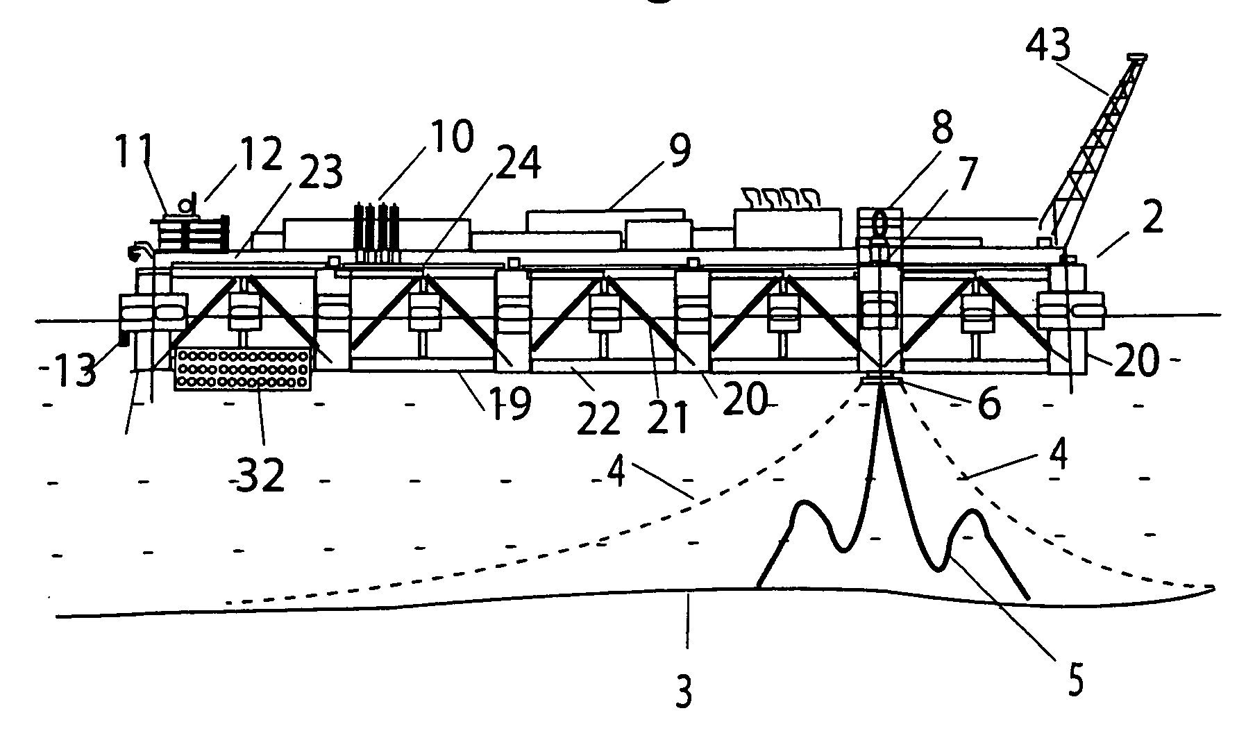
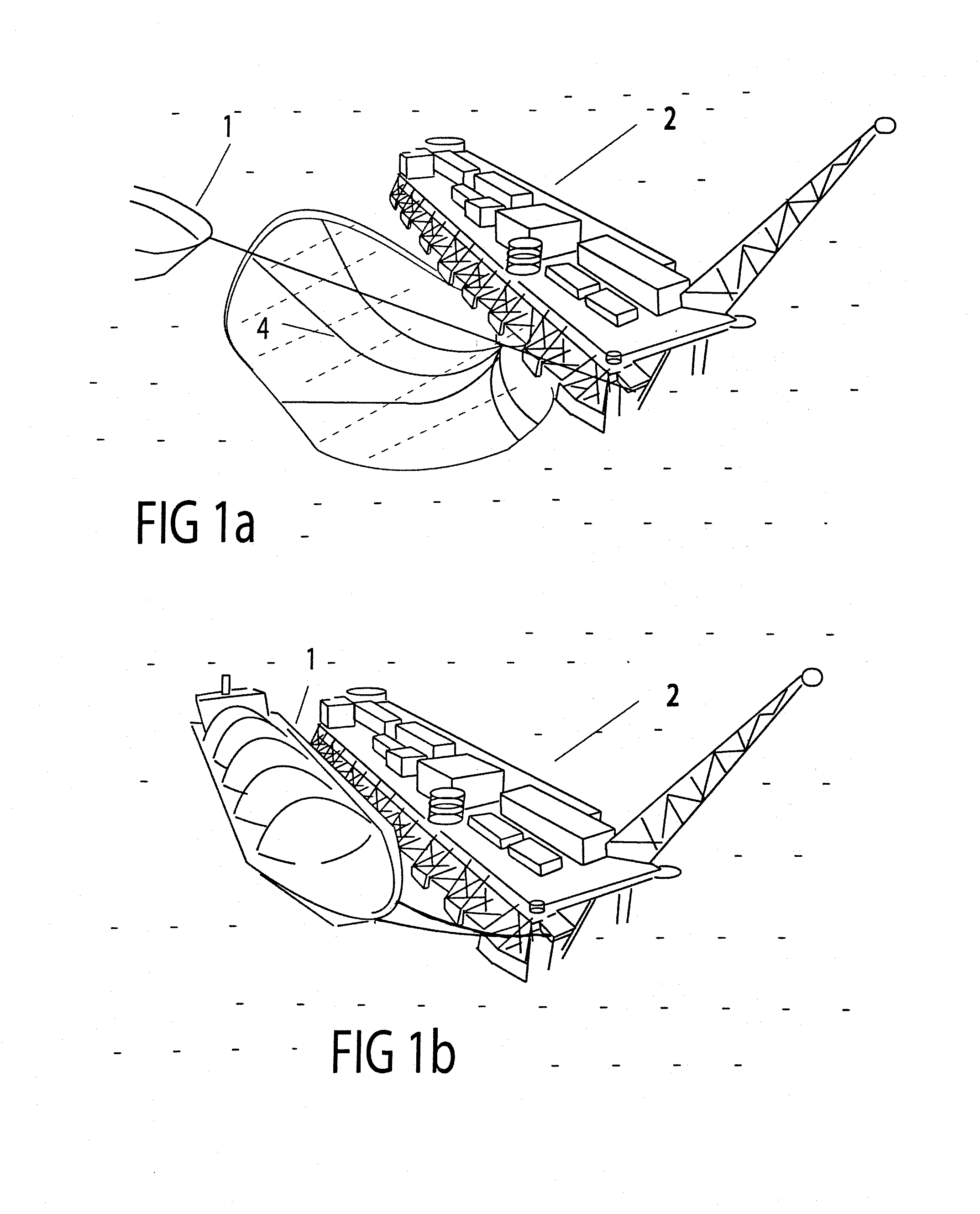
[0032]The invention is described by reference to the attached Figures where reference numbers are identified as follows:[0033]1 LNG Carrier[0034]2 Floating LNG Terminal[0035]3 Seafloor[0036]4 Anchor leg(s)[0037]5 Flexible conductor(s)[0038]6 Chaintable[0039]7 Mooring turret[0040]8 Gas and fluid swivel stack[0041]9 Process equipment[0042]10 LNG loading arms[0043]11 Crew quarters[0044]12 Control room[0045]13 Marine thruster[0046]14 Helipad[0047]15 Lifeboat(s)[0048]16 Blast wall(s)[0049]17 Pneumatic fender[0050]18 Fender support(s[0051]19 Dock frame[0052]20 Column[0053]21 Diagonal structural member(s)[0054]22 Horizontal structural member(s), pontoons[0055]23 Drop-in deck section[0056]24 Loading arm deck[0057]30 Hawser pull-in winch system[0058]31 Hawser[0059]32 Aft swing arc[0060]33 Reference line tangent to LNG carrier side[0061]34 Arc of travel of fender[0062]35 Tugboat[0063]36 LNG carrier manifold[0064]37 Arc of travel of LNG loading arms[0065]38 Mooring line(s)[0066]39 Hawser fairl...


PUM


Abstract

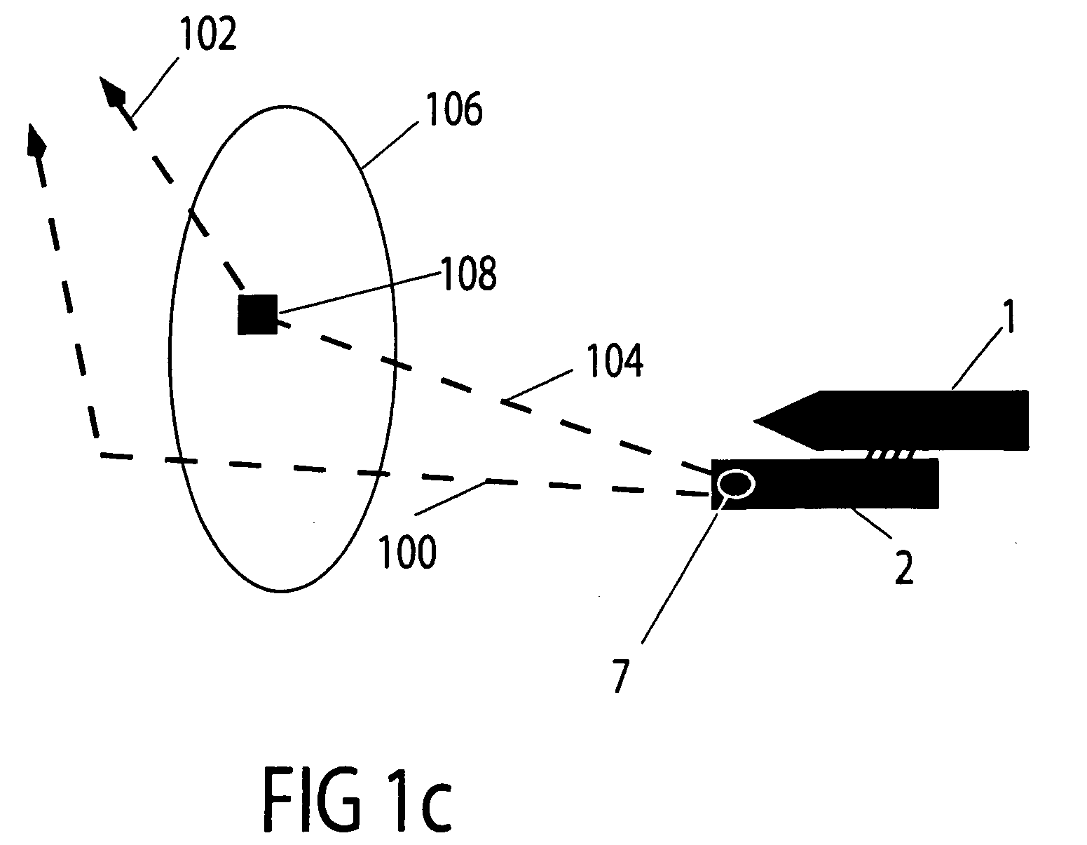
A floating terminal for offloading an LNG carrier vessel in the sea. The floating terminal of open frame construction is moored toward its front end with a rotatable mooring arrangement so that the terminal may weathervane in response to environmental forces. Marine thrusters are provided at the aft end of the terminal for swinging the terminal away from and back toward a line defined by the path toward the terminal of an approaching LNG carrier. Offloading equipment and heat exchangers are provided on a deck of the floating structure. When an LNG carrier vessel approaches the terminal, the thrusters swing the floating terminal away from the carrier vessel approach line while a hawser at the front end of the terminal pulls the vessel close to the terminal. The floating terminal swings back toward the carrier vessel in response to operating the marine thrusters in an opposite direction until the carrier vessel and floating terminal are side-by-side. The hawser continues to pull the carrier vessel forward with respect to the terminal until loading arms at the side of the terminal are aligned side-by-side with a manifold of the carrier vessel.

Description

CROSS REFERENCE TO RELATED APPLICATIONS[0001]This non-provisional application claims priority from Provisional Application 60 / 550,879 filed Mar. 5, 2004 and 60 / 554,473 filed Mar. 18, 2004.BACKGROUND OF THE INVENTION[0002]1. Field of the Invention[0003]The rapidly rising demand for energy in many countries requires an increasing level of importation of liquefied natural gas (LNG). This invention relates generally to LNG import terminals that are located offshore in water depths suitable for ship navigation. More specifically the invention concerns an LNG import terminal of open frame construction that can weathervane about a rotatable mooring structure at one end and can be rotated away from or toward a path of a docking carrier vessel to the terminal in response to operation of thrusters located at the opposite end of the terminal. Still more specifically, the invention concerns an offshore docking facility that is used advantageously in conjunction with the underground storage of h...

Claims


Application Information

Patent Timeline
Patent Type & Authority Patents(United States)
IPC IPC(8): B63B21/50B63B35/44B63B21/00B63B22/02
CPCB63B21/50
Inventor BOATMAN, L. TERRYLIU, YONGHUI
Owner SOFEC
Learn More