Fiber extrusion pack including split distribution plates

a technology of fiber extrusion pack and distribution plate, which is applied in the direction of spinnerette pack, dough shaping, manufacturing tools, etc., can solve the problems of limiting the density of pattern design in the distribution plate and thus the density of spin holes, and the limitation of design density,

Active Publication Date: 2007-11-27
HILLS CO
View PDF2 Cites 31 Cited by
  • Summary
  • Abstract
  • Description
  • Claims
  • Application Information

AI Technical Summary

Benefits of technology

[0013]According to the present invention, a fiber extrusion pack for extruding molten material to form an array of fibers comprises a plurality of split distribution plates arranged in a stack, such that each split distribution plate comprises a layer within the fiber extrusion pack, and features on the split distribution plates form a distribution network that delivers the molten material to orifices in the fiber extrusion pack. Each of the split distribution plates comprises a plurality of plate segments with a gap disposed between adjacent plate segments, and adjacent edges of the plate segments are shaped to form reservoirs along the gap. For example, opposing recesses can be respectively formed in the adjacent edges of the plate segments to form the reservoirs. Sealing plugs are disposed in the reservoirs to prevent leakage of the molten material from the fiber extrusion pack.

Problems solved by technology

In spunbond packs over one meter long, there is a limit to design density due to the inherent alignment inaccuracy at the ends of the pack.
These tolerances significantly limit the density of the pattern design in the distribution plates and thus the spin hole density, since the features on the plates must be large enough to accommodate potential misalignments of this size.
While plate-to-plate alignment accuracy can be improved somewhat by reducing manufacturing tolerances, there are inherent limitations to manufacturing accuracies, and greater accuracy requirements generally increase manufacturing costs.

Method used


Image

  • Fiber extrusion pack including split distribution plates
  • Fiber extrusion pack including split distribution plates
  • Fiber extrusion pack including split distribution plates

Examples


Embodiment Construction

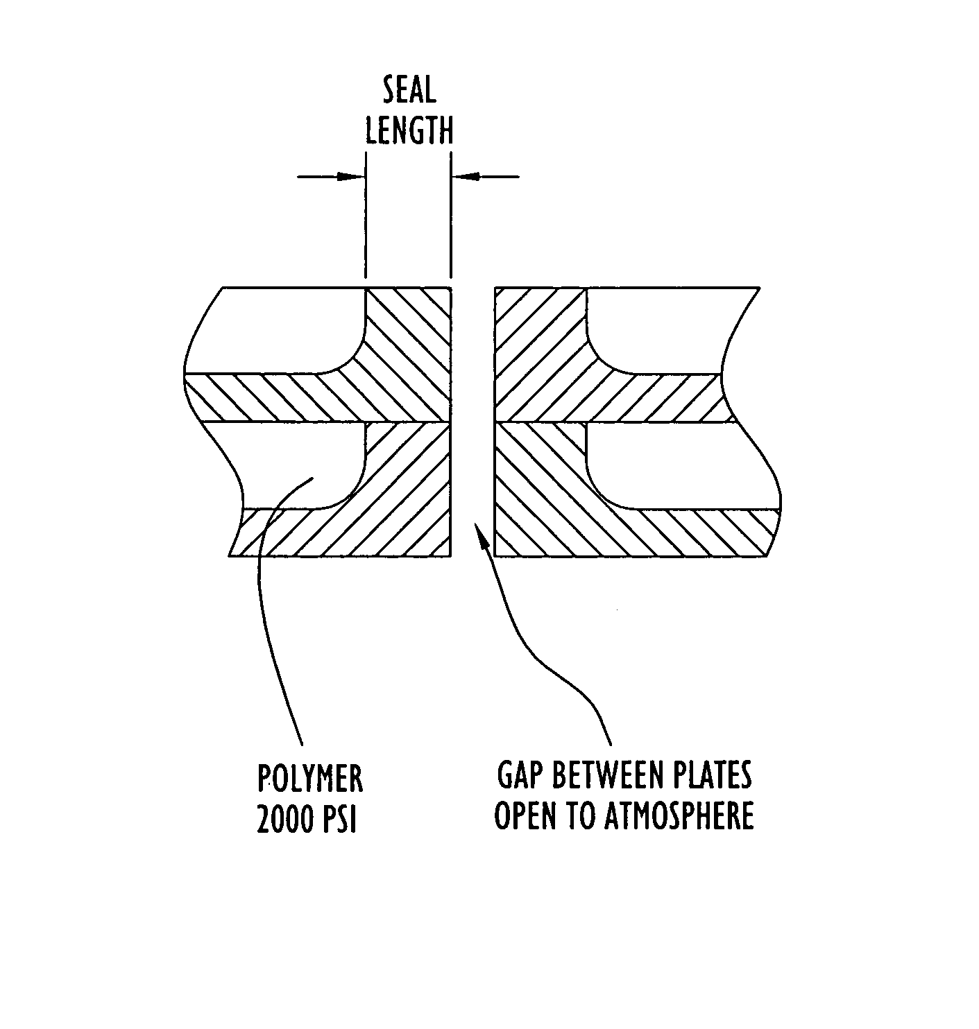
[0031]The following detailed explanations of FIGS. 2-11 and of the preferred embodiments reveal the methods and apparatus of the present invention. As used herein, the term “spin pack,”“fiber extrusion pack,” or simply “pack” refers to the assembly for processing the molten polymer to produce extruded polymer streams, including final polymer filtration, distribution systems and the spinneret. As used herein, the term “spinneret” refers to the portion of the spin pack that delivers the molten polymer to and through orifices for extrusion into the environment. The spinneret can be implemented with holes drilled or etched through a plate or any other structure capable of issuing the required fiber streams.

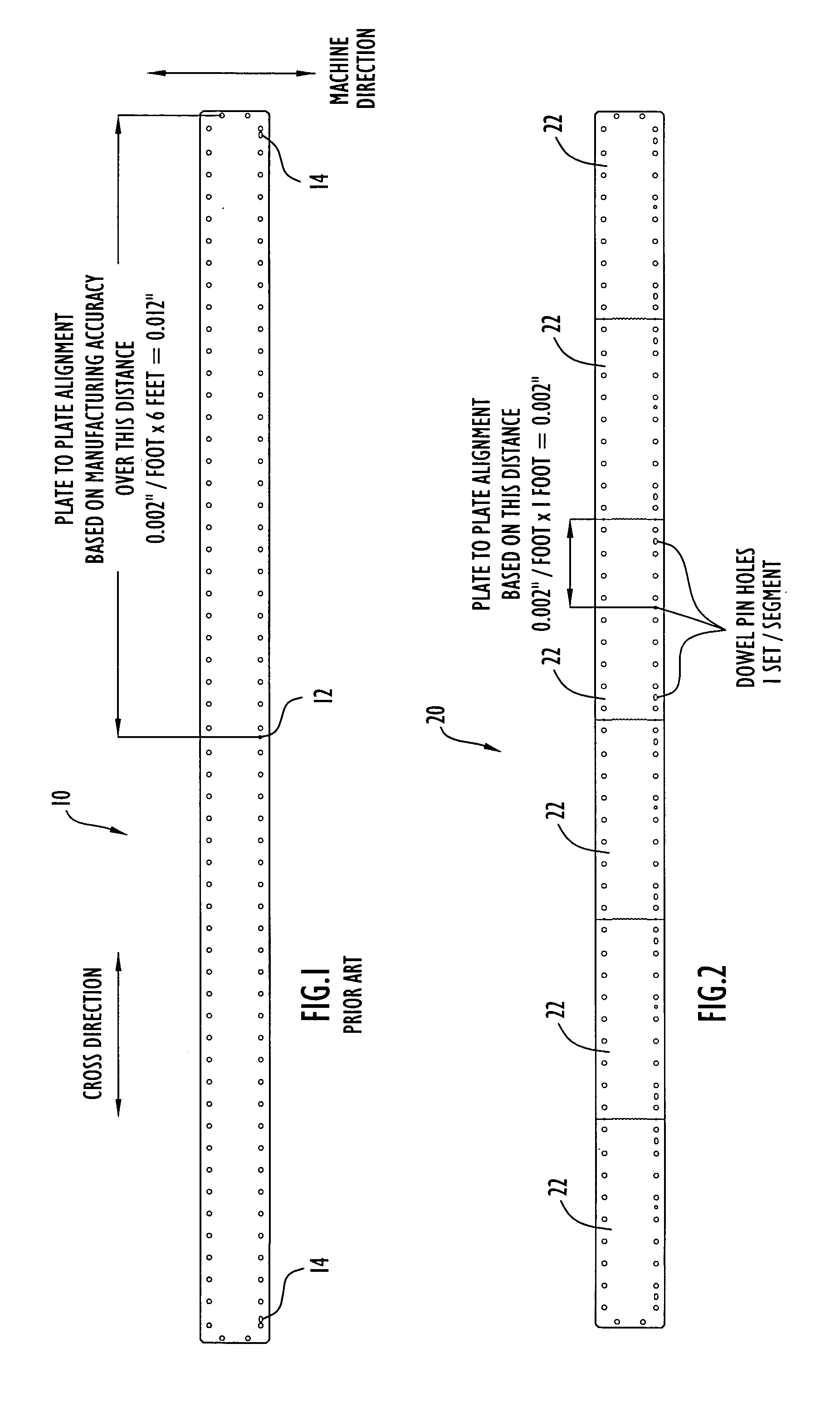
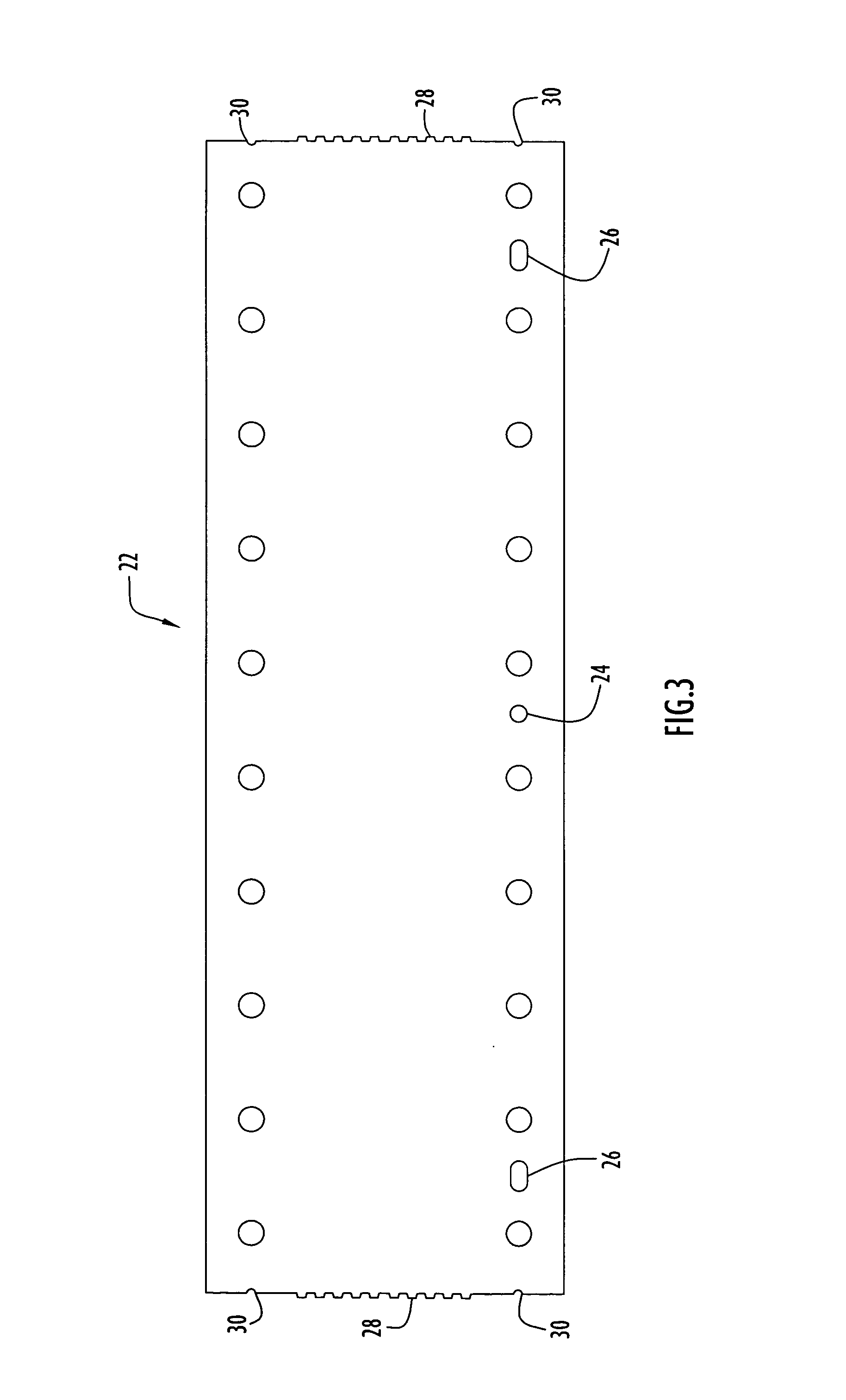
[0032]In accordance with the invention, the layers of a fiber extrusion pack comprise split, multi-piece distribution plates instead of continuous, single-piece distribution plates. Each piece or segment of the plate has its own set of dowel pins which controls the plate-to-plate alig...


PUM

PropertyMeasurementUnit
lengthaaaaaaaaaa
lengthaaaaaaaaaa
distanceaaaaaaaaaa

Abstract

A fiber extrusion pack for extruding molten material to form an array of fibers includes a number of split distribution plates arranged in a stack such that each split distribution plate forms a layer within the fiber extrusion pack, and features on the split distribution plates form a distribution network that delivers the molten material to orifices in the fiber extrusion pack. Each of the split distribution plates includes a set of plate segments with a gap disposed between adjacent plate segments. Adjacent edges of the plate segments are shaped to form reservoirs along the gap, and sealing plugs are disposed in the reservoirs to prevent the molten material from leaking from the gaps. The sealing plugs can be formed by the molten material that leaks into the gap and collects and solidifies in the reservoirs or by placing a plugging material in the reservoirs at pack assembly.

Description

CROSS REFERENCE TO RELATED APPLICATION[0001]This application claims priority from U.S. Provisional Patent Application Ser. No. 60 / 441,777, entitled “Fiber Extrusion Pack Split Distribution Plates,” filed Jan. 23, 2003. The disclosure of this provisional patent application is incorporated herein by reference in its entirety.BACKGROUND OF THE INVENTION[0002]1. Field of the Invention[0003]The present invention relates to synthetic fiber extrusion packs and polymer distribution plates for fiber extrusion packs.[0004]2. Description of the Related Art[0005]Fabrics made from melt-spinnable polymers are commonly produced using spunbond processes. The term spunbond refers to a process of forming a non-woven fabric or web from an array of thin, melt-spun polymeric fibers or filaments produced by extruding molten polymer from orifices. In a typical, large production spunbond machine, polymer pellets placed in a hopper are fed to a screw extruder which melts the polymer. The molten polymer then...

Claims


Application Information

Patent Timeline
Patent Type & Authority Patents(United States)
IPC IPC(8): B29C47/30B29C48/345B29C48/05
CPCB29C47/0014D01D4/06B29C47/30B29C48/05B29C48/345
Inventor HAGGARD, JEFFREY S.
Owner HILLS CO
Why Eureka
Try Eureka