Particle beam irradiation system

a particle beam and beam irradiation technology, applied in the field of particle beam irradiation system, can solve the problems of slight response delay and response delay

Active Publication Date: 2007-11-27
HITACHI LTD
View PDF7 Cites 178 Cited by
  • Summary
  • Abstract
  • Description
  • Claims
  • Application Information

AI Technical Summary

Benefits of technology

[0005]In the known particle beam irradiation system described above, a dose monitor for measuring a beam dose distribution and a beam position monitor are disposed within the irradiation device at a position downstream of the magnet and immediately upstream of the patient as an irradiation object (target) so that exposure to normal tissue is minimized and irradiation therapy is performed in a normal manner without causing excess or deficient dose.
[0007]Accordingly, an object of the present invention is to provide a particle beam irradiation system capable of ensuring a more uniform dose distribution at an irradiation object.
[0009]With the present invention, when the sum of the first dose and the second dose reaches the setting dose, the beam extraction stop signal is outputted to stop the extraction of the charged particle beam irradiated to the second exposure position. Therefore, the dose irradiated to the first exposure position during a period in which the extraction of the charged particle beam from the accelerator is actually stopped after the output of the beam extraction stop signal can be added to the dose measured as being irradiated to the second exposure position. As a result, the dose irradiated to each exposure position can be held substantially equal to the setting dose, and a dose distribution at the irradiation object can be made more uniform even when a certain time is required from the output of the beam extraction stop signal to the time when the extraction of the charged particle beam from the accelerator is actually stopped.
[0011]Thus, according to the present invention, a dose distribution at the irradiation object can be made more uniform even when a certain time is required from the output of the beam extraction stop signal to the time when the extraction of the charged particle beam from the accelerator is actually stopped.

Problems solved by technology

However, the inventors have found a possibility that, in the accelerator, a slight response delay occurs after the input of the beam extraction stop signal to the accelerator.
As a result, even with the beam extraction stop signal inputted as mentioned above, the extraction of the charged particle beam is not stopped at once in the strict sense and a slight response delay occurs.

Method used


Image

  • Particle beam irradiation system
  • Particle beam irradiation system
  • Particle beam irradiation system

Examples


first embodiment

[0026]A particle beam irradiation system according to the present invention will be described below with reference to the drawings.

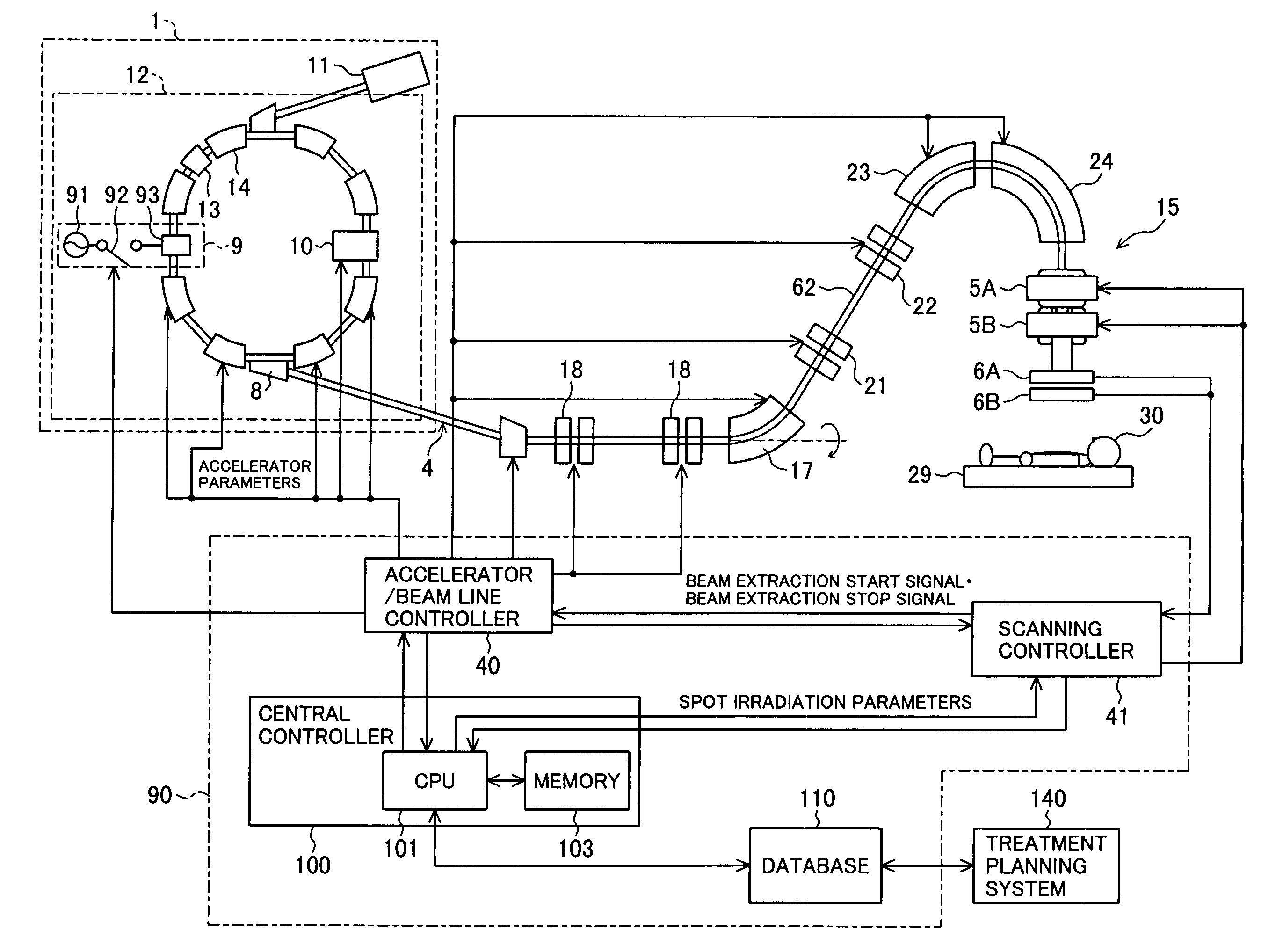
[0027]As shown in FIG. 1, a proton beam irradiation system, i.e., one example of the particle beam irradiation system according to the first embodiment of the present invention, comprises a charged particle beam generator 1 and a beam line 4 connected downstream of the charged particle beam generator 1.

[0028]The charged particle beam generator 1 comprises an ion source (not shown), a pre-stage charged particle beam generator (linac) 11, and a synchrotron (accelerator) 12. The synchrotron 12 comprises an RF knockout device 9 and an accelerating unit 10. The RF knockout device 9 includes an RF knockout electrode 93 disposed in a circulating orbit in the synchrotron 12 and an RF power supply 91, which are connected to an on / off switch 92. The accelerating unit 10 includes an RF cavity (not shown) disposed in the circulating orbit, and an RF power supply (no...

second embodiment

[0092]In the second embodiment, the dose irradiated during the period of response delay in the synchrotron 12 with respect to the irradiation to a certain spot is assumed to be included in the dose irradiated to the next spot, and based on such an assumption, the ion beam is irradiated to the next spot until reaching the target dose for the next spot. However, the following other methods (1) and (2) can also provide the similar advantages.

[0093](1) In step 309 executed by the preset counter 41a, from the target dose for a certain spot, the dose irradiated during the period of response delay with respect to the irradiation to the preceding spot is subtracted, and the count number during the irradiation to the certain spot is further subtracted from the remaining dose. Then, when the remaining dose after the two subtractions becomes 0, the trigger signal is outputted in step 310.

[0094](2) The target count number set by the preset counter in step 302 is given as the dose obtained by su...


PUM


Abstract

A particle beam irradiation system capable of ensuring a more uniform dose distribution at an irradiation object even when a certain time is required from output of a beam extraction stop signal to the time when extraction of a charged particle beam from an accelerator is actually stopped. The particle beam irradiation system comprises a synchrotron, an irradiation device including scanning magnets and outputting an ion beam extracted from the synchrotron, and a control unit. The control unit stops the output of the ion beam from the irradiation device in accordance with the beam extraction stop signal, controls the scanning magnets to change an exposure position in a state in which the output of the ion beam is stopped, and after the change of the exposure position, starts the output of the ion beam from the irradiation device again. The control unit further outputs a next beam extraction stop signal when an increment of dose integrated from the time of a preceding beam extraction stop signal as a start point reaches a setting dose stored in advance.

Description

BACKGROUND OF THE INVENTION[0001]1. Field of the Invention[0002]The present invention relates to a particle beam irradiation system, and more particularly to a particle beam irradiation system for irradiating a charged particle beam, such as a proton or carbon ion beam, to an affected part of the body for treatment.[0003]2. Description of the Related Art[0004]There is known a therapy method of irradiating a charged particle beam (ion beam), such as a proton or carbon ion beam, to an affected part, e.g., a cancer, in the body of a patient. A particle beam irradiation system for use with such a therapy method comprises a charged particle beam generator, a beam line, and a treatment room. The charged particle beam accelerated by an accelerator in the charged particle beam generator reaches an irradiation device in the treatment room through the beam line, and it is irradiated to the affected part of the patient body from the irradiation device after being scanned by a scanning magnet d...

Claims


Application Information

Patent Timeline
Patent Type & Authority Patents(United States)
IPC IPC(8): G21K5/10G21G5/00
CPCA61N5/1043A61N5/1048A61N2005/1087
Inventor MATSUDA, KOJINAKAYAMA, TAKAHIDE
Owner HITACHI LTD
Why Eureka
Try Eureka