Test head for optically inspecting workpieces

a test head and workpiece technology, applied in the direction of optical elements, instruments, optical waveguide light guides, etc., can solve the problems of requiring considerable effort to make or adjust such apparatuses, and achieve the effects of reducing or eliminating unwanted diffracted light, reducing or eliminating diffracted light, and reducing stray ligh

Inactive Publication Date: 2007-11-27
WD MEDIA
View PDF18 Cites 69 Cited by
  • Summary
  • Abstract
  • Description
  • Claims
  • Application Information

AI Technical Summary

Benefits of technology

[0013]At least one of the optical paths is an output path for permitting light reflected by the substrate to travel from the substrate to one or more detectors within, affixed to, or proximate to the block. The output paths can comprise one or more optical elements such as lenses for collecting reflected light from the substrate, lenses for concentrating light onto a detector, mirrors for altering the direction of the light, and absorbers, masks, and / or irises for reducing stray light.
[0014]In one embodiment, one or more masks are provided in one or more output paths to reduce or eliminate unwanted diffracted light caused by the texture formed on the substrate. In another embodiment, the apparatus is used to inspect an untextured disk comprising a pattern formed on the disk for discrete track recording. In such an embodiment the masks can reduce or eliminate diffracted light caused by the pattern.

Problems solved by technology

Accordingly, considerable effort is required to make or adjust such apparatus.

Method used


Image

  • Test head for optically inspecting workpieces
  • Test head for optically inspecting workpieces
  • Test head for optically inspecting workpieces

Examples


Embodiment Construction

I. Overview of Optical Inspection Apparatus 10

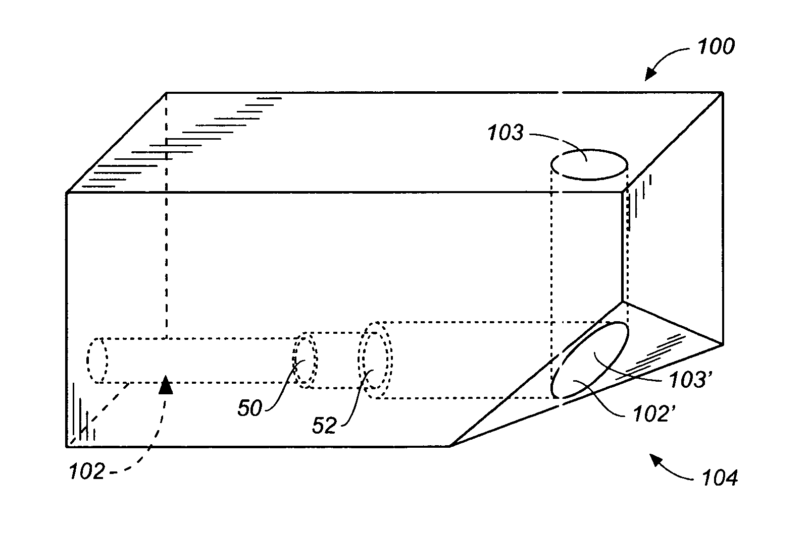
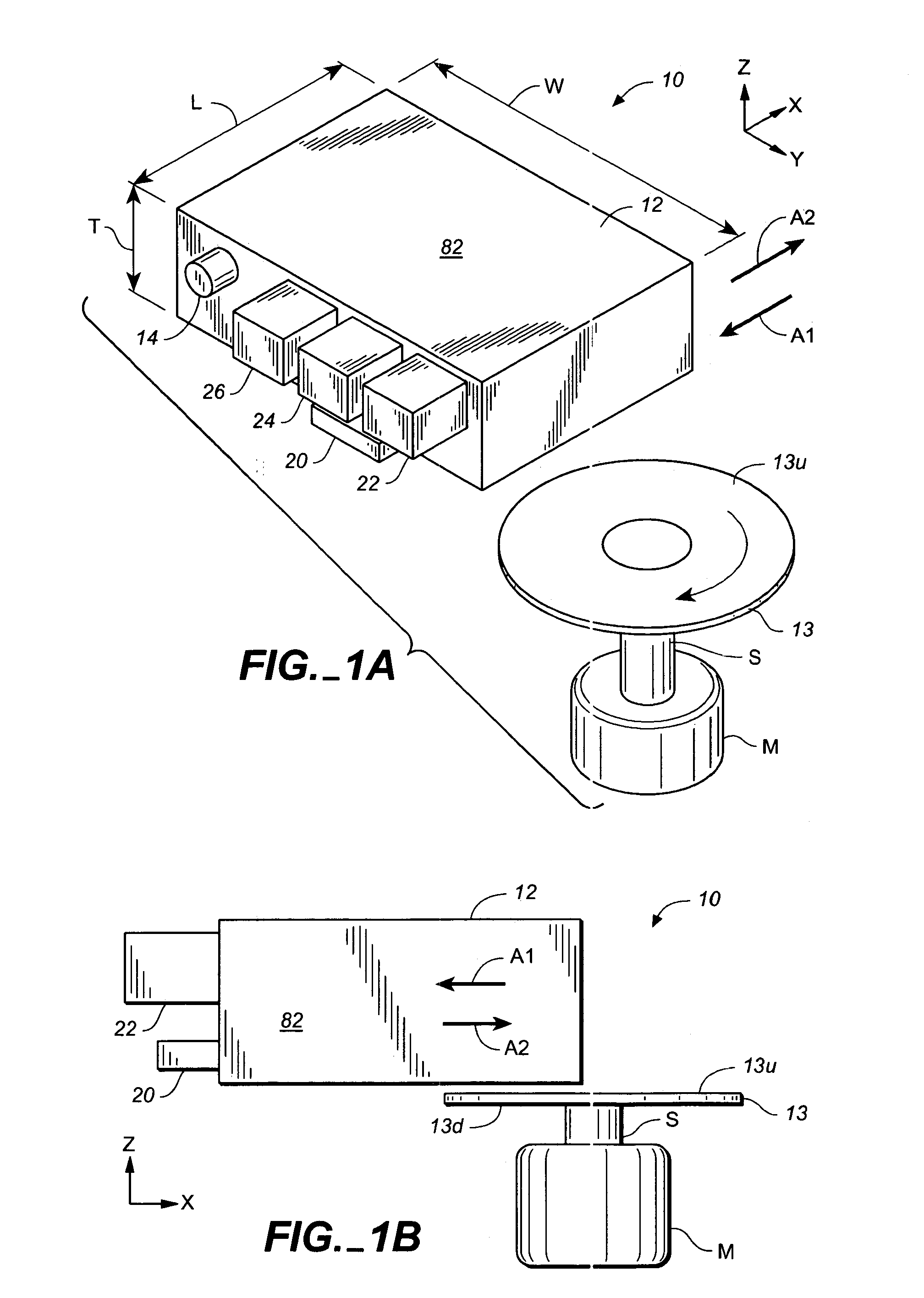
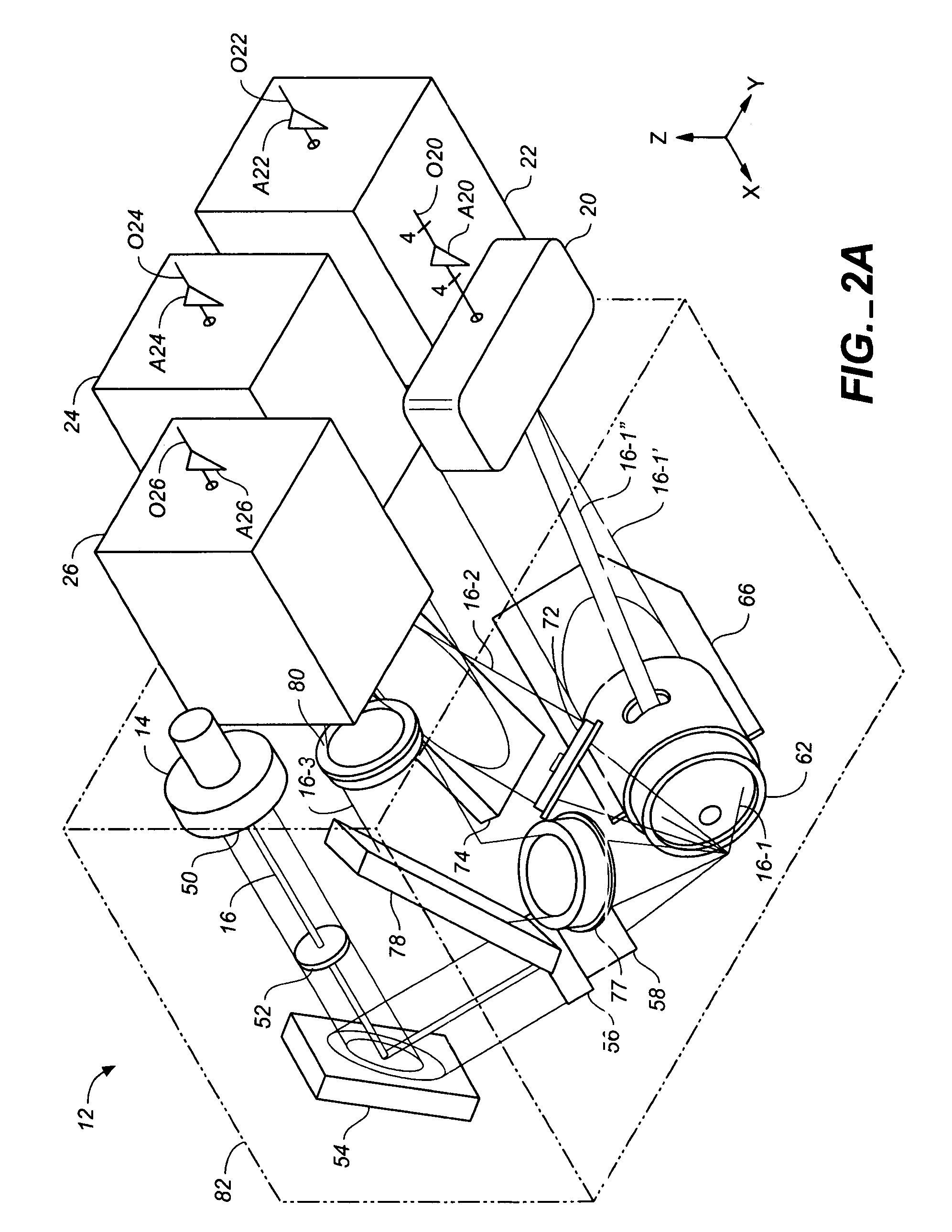
[0041]FIGS. 1A, 1B, 2A and 2B schematically illustrate an example of an optical inspection apparatus 10 in accordance with the invention that includes a head 12 for optically inspecting a top surface 13u of a workpiece 13 (typically a platter). (FIGS. 1A and 1B show the exterior of head 12 in schematic form. The actual appearance of head 12, in one embodiment, is shown in FIGS. 3A to 3D. FIGS. 2A and 2B show the optical paths and elements within head 12.) Head 12 comprises a laser source 14 for providing a laser beam 16. Head 12 also includes a) a set of lenses, masks, mirrors and other optical elements (described below) for modifying laser beam 16 and directing and focusing beam 16 onto a spot on surface 13u; and b) a set of mirrors, lenses and other optical elements (also described below) for modifying and directing light reflected by surface 13u to various detectors 20-26 (discussed below). (As used herein, “reflected” includes specul...


PUM

PropertyMeasurementUnit
angleaaaaaaaaaa
angleaaaaaaaaaa
angle of incidenceaaaaaaaaaa

Abstract

An optical test head comprises a block of material with a plurality of optical paths extending therethrough. At least one of the optical paths is an input optical path for receiving laser light and holding a lens for focusing the laser light on a workpiece that is proximate the head. At least another of the optical paths is an output path for receiving light that is reflected off of the workpiece and providing that light to a detector. (In one embodiment, several detectors are provided to direct specularly reflected light, narrow angle scattered light, wide angle scattered light and back scattered light to associated detectors.) Other optical elements can be affixed within or to the block of material. The test head can be used without requiring the individual optical elements to be aligned or adjusted.

Description

CROSS-REFERENCE TO PROVISIONAL PATENT APPLICATION[0001]This application claims priority based on U.S. provisional patent application No. 60 / 643,748, filed Jan. 13, 2005.BACKGROUND OF THE INVENTION[0002]This invention relates to methods and apparatus for optically inspecting workpieces such as substrates used to make magnetic disks or magnetic disks during any point in the manufacturing process (including the finished disk). This invention also pertains to methods for making such apparatus.[0003]Magnetic disks are typically manufactured using the following method.[0004]1. A disk-shaped substrate (typically an Al alloy) is lapped or ground.[0005]2. A material such as a nickel phosphorus alloy is plated onto the substrate.[0006]3. The plated substrate is polished and textured. (During texturing, texture grooves are typically formed in the substrate by mechanical abrasion to cause a subsequently deposited magnetic layer to exhibit anisotropy. It is also known to laser texture substrates...

Claims


Application Information

Patent Timeline
Patent Type & Authority Patents(United States)
IPC IPC(8): G02B6/34G01N21/01G02B27/10
CPCG01N21/47G01N21/95G01N21/8806G11B5/8404G01N21/9506G01N21/9501
Inventor TREVES, DAVIDO'DELL, THOMAS A.
Owner WD MEDIA
Why Eureka
Try Eureka