Pressurized plastic bottle with reinforced neck and shoulder for dispensing an aerosol

a plastic bottle and aerosol technology, applied in the field of dispensers, can solve the problems of plastic container deformation, container unsightly appearance, plastic container features deformation, etc., and achieve the effect of reducing the external concavity of the container, minimizing the effect of creep deformation over time, and reducing the creep deformation

Active Publication Date: 2007-12-04
SC JOHNSON & SON INC
View PDF19 Cites 160 Cited by
  • Summary
  • Abstract
  • Description
  • Claims
  • Application Information

AI Technical Summary

Benefits of technology

[0009]The present invention is directed toward a pressure resistant plastic bottle for containing and dispensing an aerosol composition which includes a reinforcement to its neck region to reduce creep deformation so as to eliminate the previously inherent instability of this region of the plastic bottle. The plastic bottle is comprised of a hollow elongate body having a longitudinal axis and an outer wall. The outer wall defines a neck having an opening therein for receiving and dispensing an aerosol composition. A flange projects radially outwardly from the neck and divides the neck into an upper portion and a lower portion. Local reinforcement of the lower neck portion effectively resists the internal pressures generated by an aerosol to reduce creep deformation and prevent the instability of this region of the bottle.
[0011]In another aspect of the invention, the local reinforcement can be defined by comparing the wall thickness of the lower neck portion to the radial thickness of the projecting flange. Thus, in order to reduce creep deformation, the reinforcement of the lower neck portion comprises the wall thickness of the lower portion being from about 0.55 to about 1 times the radial thickness of the flange. Preferably, the reinforcement comprises the wall thickness of the lower neck portion being about 0.6 to about 0.8 times the radial thickness of the flange, and most preferably the reinforcement comprises the wall thickness of the lower portion being about 0.7 times the radial thickness of the flange. Thus, the ratio of the wall thickness of the lower neck portion compared to the radial thickness of the flange ranges between a ratio of from about 0.55:1 to about 1:1, preferably from about 0.6:1 to about 0.8:1 and most preferably about 0.7:1. Again, as previously noted, such a design for the lower neck portion and flange provides a neck region which effectively resists the internal pressures generated by an aerosol to minimize any creep deformation effects over time. This design thus provides a neck region which reduces the external concavity thereof and minimizes abrupt changes in the configuration of the neck region to minimize the inherent weakness of the neck region.

Problems solved by technology

Despite the desirability of using plastic containers for aerosols, there are some inherent disadvantages to utilizing plastic materials in such an environment.
The areas of such abrupt changes are stress concentration points which are inherently weak.
Another disadvantage is that when the container is subject to internal pressure, certain features of a plastic container may deform.
As a result of such stress, slight bulging and / or skewing of a container may occur causing the container to become unsightly, and depending on the location of the deformation, the container could become unstable and may not rest properly on a table or other flat surface.
Conventional PET or PET / PEN aerosol bottles tend to be unable to hold pressure without distortion at elevated temperatures due to two fundamental weaknesses.
First, the neck region is amorphous and will undergo large, irreversible, time-dependent deformations known as “creep.” Secondly, the neck region is composed of an externally concave shell configuration which is inherently unstable under internal pressure.
The stress crazing will typically occur in the neck region slightly above the shoulder of a molded PET container because this region does not achieve enough orientation during the blow molding process.
If this stress is higher than the yield stress of the material, structural deformation and failure may occur.
However, for amorphous PET (such as that found in the neck region) the yield strength and Youngs modulus is about ⅛ that of orientated PET, which as noted above, results in poor mechanical properties.
Reducing the diameter of the container, however, provides other disadvantages because such a container becomes more difficult to injection and blow mold, and may provide a product container of undesirable dimensions and volume.
Likewise, increasing sidewall thickness creates its own unique problems, such as undesirably increasing cycle time and propensity to crystallize the PET due to slow cooling of thicker sidewalls.

Method used


Image

  • Pressurized plastic bottle with reinforced neck and shoulder for dispensing an aerosol
  • Pressurized plastic bottle with reinforced neck and shoulder for dispensing an aerosol
  • Pressurized plastic bottle with reinforced neck and shoulder for dispensing an aerosol

Examples


Embodiment Construction

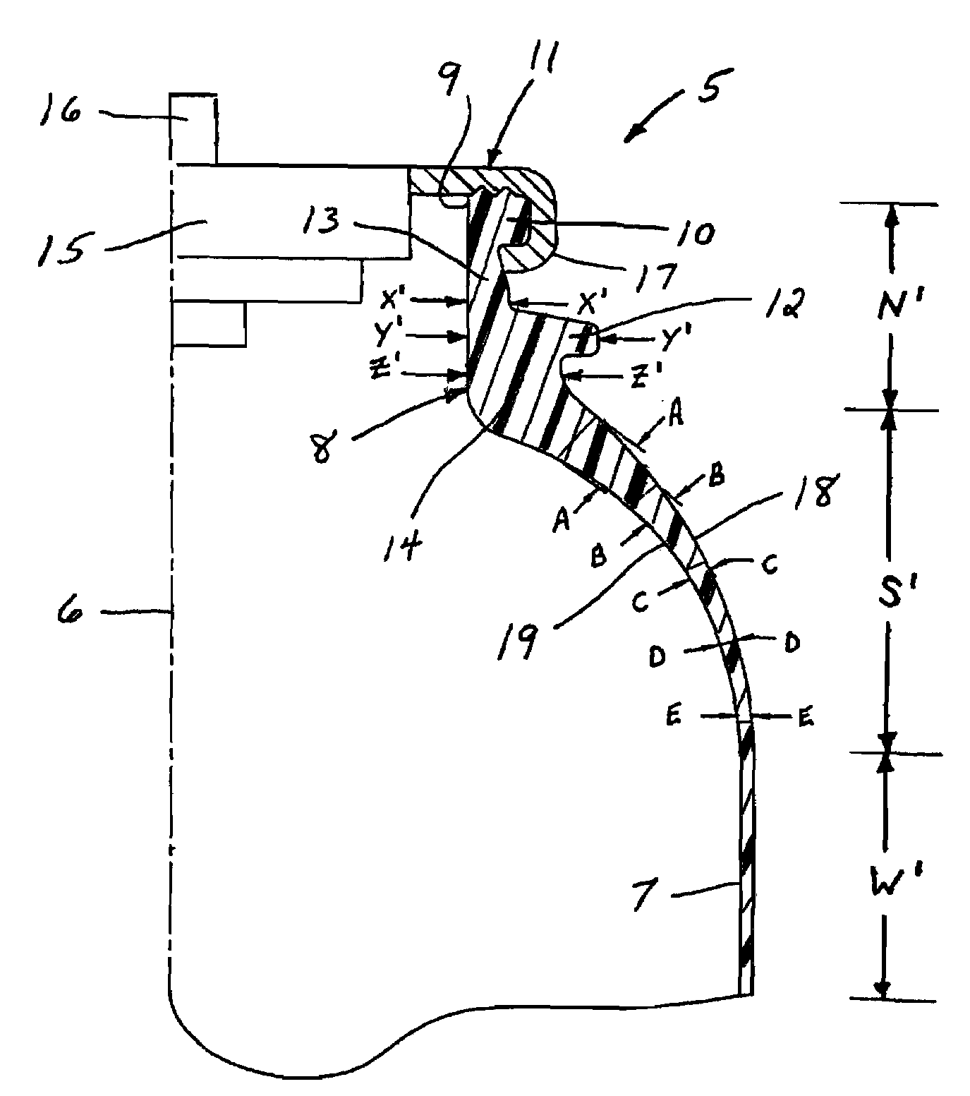
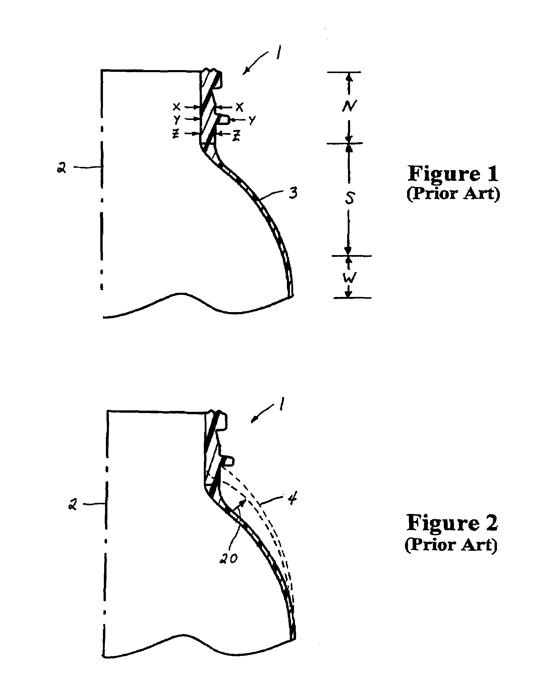
[0017]Referring now to the drawings, there is illustrated in FIG. 1 a prior art pressure resistant plastic bottle generally designated by the numeral 1 for containing and dispensing an aerosol composition. The plastic bottle 1 comprises a hollow elongate body having a longitudinal axis 2 and an outer wall 3. Bottle 1 may be divided into a plurality of regions or portions, namely, a neck portion N, a shoulder portion S, a waist portion W, a generally cylindrical elongate body portion (not shown) and a closed bottom portion (not shown). Each of these portions is integral with the other and is formed as a one-piece construction. Bottle 1 is designed to contain an aerosol composition (not shown) which is typically pressurized at an internal pressure of from about 275.8 kPa (40 psi) to about 620.5 kPa (90 psi). Examples of typical aerosol compositions are insecticides, insect repellants, hair sprays, air fresheners, cleaning preparations, and shave preparations including foams and gels.

[...


PUM


Abstract

A pressure resistant plastic bottle for containing and dispensing an aerosol composition. The plastic bottle is designed to reduce deformation by a local reinforcement to the neck and shoulder regions. The reinforcement preferably comprises the provision of a wall thickness for a lower portion of the neck as compared to the wall thickness of the upper portion of the neck to be increased by a ratio of from about 1.25:1 to about 2.5:1.

Description

BACKGROUND OF THE INVENTION[0001]The present invention relates to dispensers for aerosols or other pressurized products, and more particularly to a pressure resistant plastic bottle containing a reinforced neck and shoulder region for dispensing an aerosol or other comparably pressurized product.[0002]The term “aerosol” will be understood herein to encompass both aerosols, literally, and other liquid or flowable products that can be dispensed from pressurized containers in a manner comparable to aerosolized products. Such products may include but are not limited to foamed or gel preparations or to liquid products delivered in a non-aerosol stream.[0003]Pressurized containers for dispensing aerosols are well known in the art, and are typically constructed of metal in order to withstand the inherent internal pressures of aerosols. However, it is desirable to provide a plastic container capable of withstanding the internal pressures generated by an aerosol because plastic has many adva...

Claims


Application Information

Patent Timeline
Patent Type & Authority Patents(United States)
IPC IPC(8): B65D1/46B65D23/00B65D47/00B65D83/14
CPCB65D83/38
Inventor FLASHINSKI, STANLEY J.HOADLEY, DAVID A.BEDNARZ, STEPHEN M.MUKHERJEE, SUMIT
Owner SC JOHNSON & SON INC
Why Eureka
Try Eureka