Polymer control system

a control system and polymer technology, applied in the field of polymer control system, can solve the problems of insufficient sensitiveness of video image processing technology to be of use in controlling polymer dosage, inability to accurately detect, and slow change of “camera readings” to achieve the effect of lowest possible polymer cos

Active Publication Date: 2007-12-04
CHEMTRAC
View PDF1 Cites 6 Cited by
  • Summary
  • Abstract
  • Description
  • Claims
  • Application Information

AI Technical Summary

Benefits of technology

[0007]The object of the present invention is to provide an improved method and apparatus for readjusting, on-line, the rate at which polymer is fed into wastewater upstream of a gravity belt thickener, belt press or the like in such a way as to achieve optimum dewatering, whether it be measured in terms of cake dryness, filtrate clarity, volume processed, or some combination of these parameters, at the lowest possible-polymer cost.
[0009]A still further object of the present invention is to provide such an apparatus which can respond to changes in the degree of wetness of the sludge cake before drastic events occur and in so responding, increase the polymer dosage when a streaming current monitor shows a likely underfeed of polymer and decrease the polymer dosage when the SCM shows a likely overfeed of polymer.
[0010]In accordance with the present invention, there is provided an improved feedback control for a polymer dispensing system, which otherwise would continuously make adjustments to the polymer feedrate in such a way as to keep the measured streaming current of filtrate from a sludge dewatering process at a predetermined setpoint. The feedback control includes a video camera focused on a portion of the sludge cake as it trails behind dewatering plows on a gravity belt thickener or the like, a video image processing system for converting the signal from the video camera into a single number “camera reading”, a computer programmed to activate a controller which incrementally resets the rate at which polymer is being fed to the wastewater flow upstream of the belt thickener whenever the “camera reading” goes either above or below its setpoint by a predetermined threshold amount, and means for establishing a new streaming current setpoint automatically once optimum sludge dewatering conditions have been restored, as evidenced by the “camera reading” returning to a value within the threshold of the “camera reading” setpoint. In addition, the computer is programmed to determine whether the filtrate charge, as the “camera reading” begins an excursion outside its acceptable range, is more positive or more negative than the normal cationic charge in the filtrate, as measured by the SCM, and to activate the controller to incrementally decrease the polymer feedrate when the filtrate charge is more positive and increase this feedrate when the filtrate charge is more negative.

Problems solved by technology

Unfortunately, video image processing technology by itself is not sufficiently sensitive to be of use in controlling polymer dosage in dewatering systems automatically.
A significant underfeed of polymer, for example, initially causes the “camera readings” to change only slowly.
The resultant pattern while useful in helping an operator to initially set a minimum polymer dosage for a given set of process conditions, cannot be used to accurately detect, on-line, which direction polymer dosage may need to be adjusted in response to changing process conditions.
In some situations, the high frequency of required setpoint adjustments—necessitated because of certain changes in sludge composition and even changes in flow rates, especially when short retention times were involved—led operators to question the effectiveness of using streaming current monitoring technology in wastewater treatment plants (WWTPs).

Method used


Image

  • Polymer control system
  • Polymer control system
  • Polymer control system

Examples


Embodiment Construction

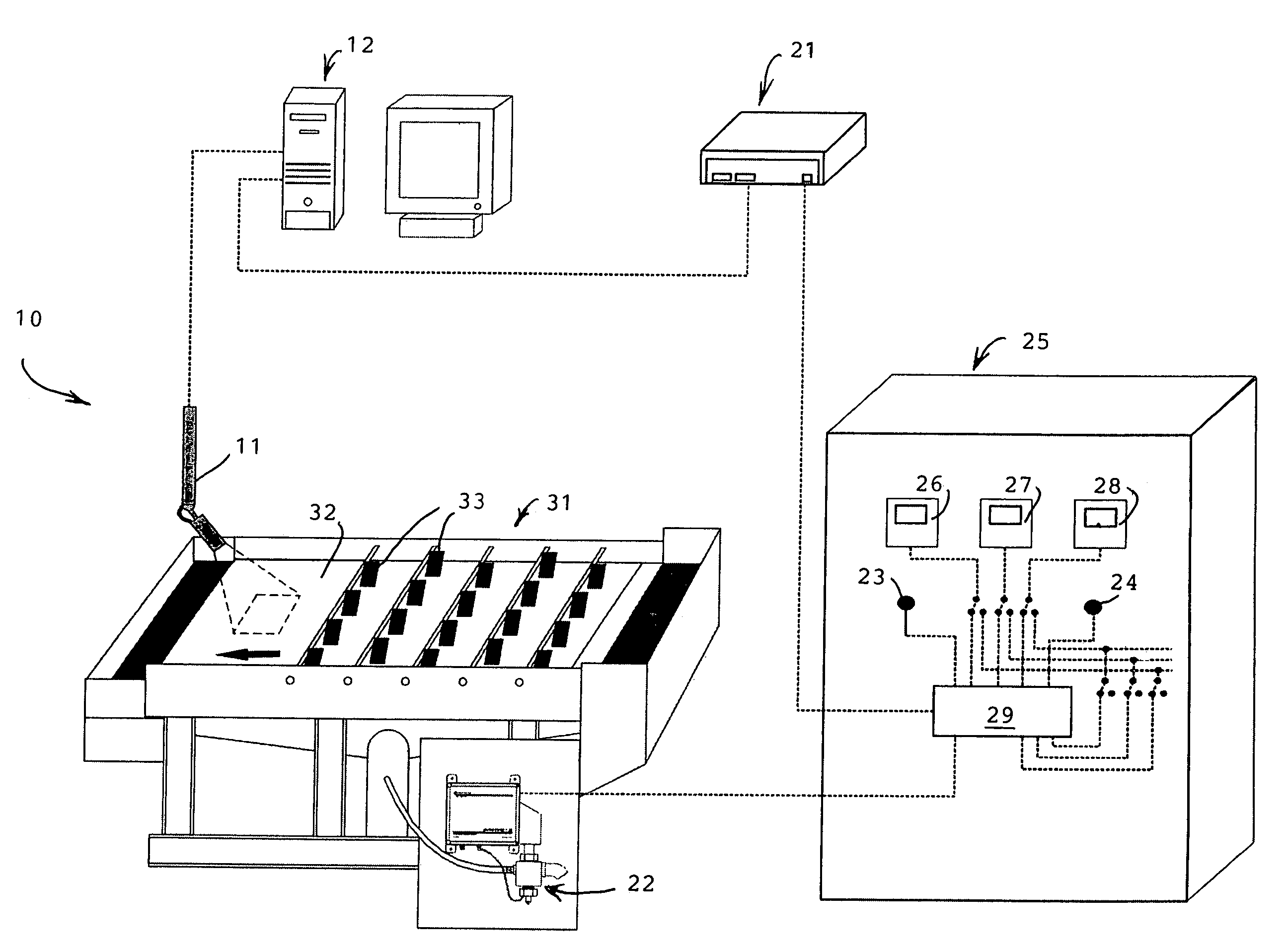
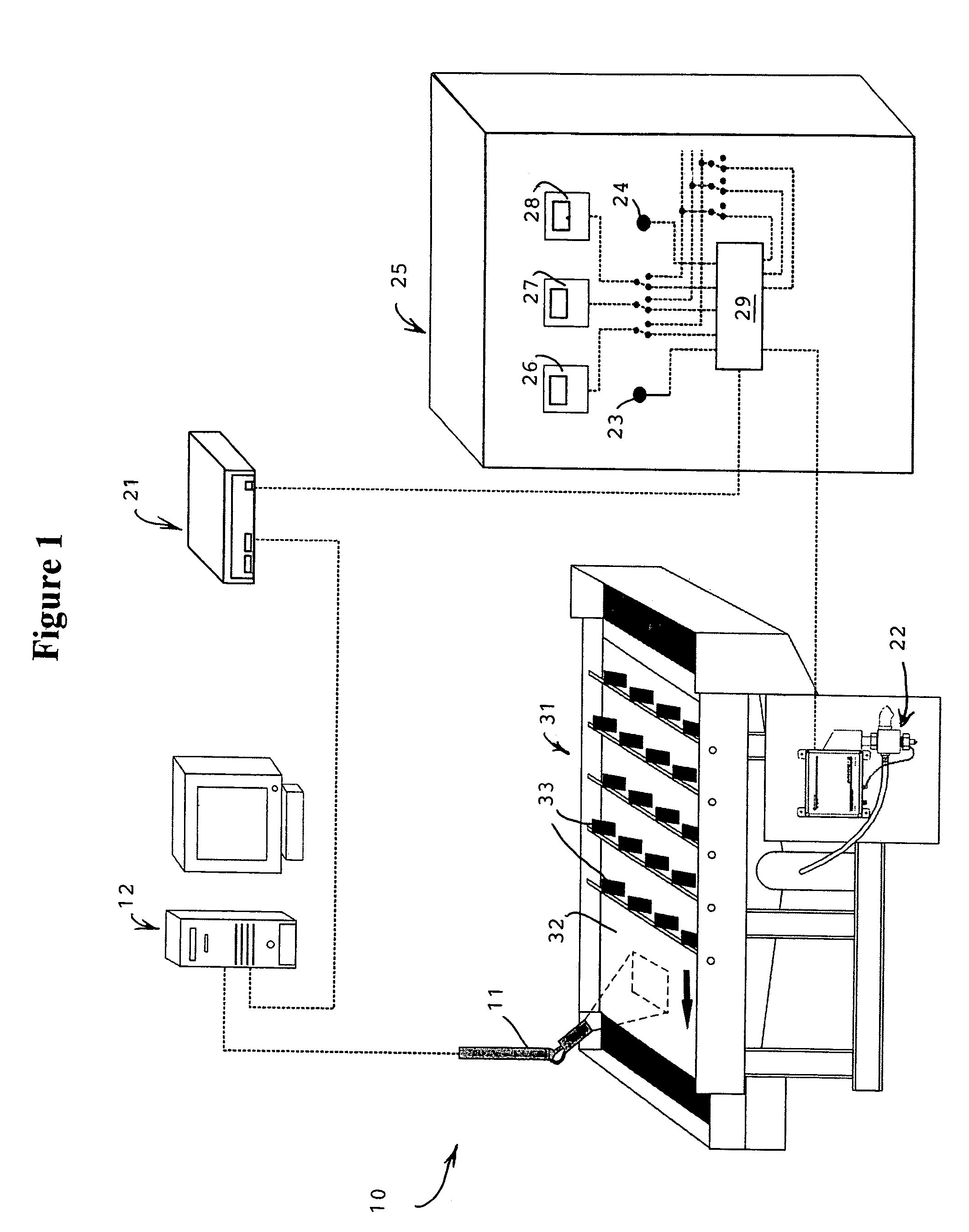
[0015]Referring to the drawings, the improved apparatus according to the present invention is denoted generally by the reference numeral 10. The apparatus 10 comprises a video camera 11 which is focused on a fixed portion of a gravity belt thickener 31, a Web access controller 21, and a streaming current monitor 22 (FIG. 1). During operation, the signal from the video camera 11, at any given moment of time, is related to a single number known as the “camera reading”; facilitating interpretation of the camera image.

[0016]In the preferred embodiment, a video monitoring system including a PC computer 12, a video input card, Polytracker™ software, and an analog output card is used to process the video signal and send 4-2.0 milliamp signals back to the Web access controller 21.

[0017]Programmed into the Polytracker™ software is a “pixel threshold” which establishes the value by which the pixels of the camera's image are divided into one or the other of two bins—black and white. Calibratio...


PUM

PropertyMeasurementUnit
lag timeaaaaaaaaaa
currentaaaaaaaaaa
streaming currentaaaaaaaaaa

Abstract

A feedback control for a polymer dispensing system, which otherwise continuously adjusts the polymer feedrate so as to keep the measured streaming current of filtrate from a sludge dewatering process at one predetermined setpoint. The feedback control includes a video camera focused on sludge as it trails behind plows on a dewatering belt, a video image processing system for converting the video signal into single numbers known as “camera readings”, and a computer programmed both to compare them with a “camera reading” setpoint and to determine whether the filtrate charge is more positive or more negative than it normally is whenever the “camera reading” deviates from its setpoint by a threshold amount. A controller, activated by the computer, incrementally resets the polymer feedrate in such a direction as to restore the normal cationic charge of the filtrate. The feedback control uses the streaming current value measured immediately after each “camera reading” excursion to update the streaming current setpoint.

Description

BACKGROUND OF THE INVENTION[0001]The present invention relates to apparatus for detecting the degree of wetness of sludge as it is being dewatered on a gravity belt thickener, belt press or the like and to controls, based on streaming current monitoring technology, for adjusting polymer dosage, on-line, in wastewater treatment processes.[0002]In the prior art, optical devices, including a video camera focused on a fixed portion of a sludge dewatering belt, have been used to identify the exact moment at which the wetline on the belt crosses a given point. Typically, this point is located after the last row of dewatering plows; and the movement of the wetline into the camera's viewing range signals that there has been a sudden change-in process conditions causing the sludge to become wet.[0003]Previously, the video camera has been used to track visually the onset of sludge dewatering systems washouts. When the sludge cake becomes wet, there are less distinct trails behind the plows; a...

Claims


Application Information

Patent Timeline
Patent Type & Authority Patents(United States)
IPC IPC(8): B01D21/00C02F11/147
CPCB01D37/03C02F1/5209C02F2209/006C02F2209/003C02F11/14C02F11/147
Inventor CLARK, JOHN W.
Owner CHEMTRAC
Why Eureka
Try Eureka