Method and apparatus for reducing Q factor in an oscillating laser scanner

a laser scanner and q factor technology, applied in the field of optical systems, can solve the problems that the scan amplitude becomes difficult to maintain at a constant level, and achieve the effects of decreasing the mass of the mirror, reducing the stiffness of the elastic member, and reducing the rotational inertia

Inactive Publication Date: 2007-12-04
LEXMARK INT INC
View PDF22 Cites 12 Cited by
  • Summary
  • Abstract
  • Description
  • Claims
  • Application Information

AI Technical Summary

Benefits of technology

[0008]The method of the invention generally increases component yields, thereby reducing component costs. Also, a laser printer using a torsion oscillator having a Q value that is reduced according to the invention may be used over a wider speed range. Conversely, a single laser printer model may be used at a single speed, rather than at speeds that vary slightly due to variations in resonant frequency. The invention also provides for greater freedom of movement of the printer operating point during printer development.
[0012]In some preferred embodiments, the method includes decreasing the mass of the mirror so that the rotational inertia, J, is decreased by up to about 50 percent, and decreasing the stiffness of the elastic members so that the spring constant, K, is decreased by up to about 50 percent. Preferably, the damping constant, C, and the resonant frequency, Fr, are substantially unchanged.

Problems solved by technology

Otherwise, its scan amplitude becomes difficult to maintain at a constant level with feedback control and reasonable amounts of drive power.

Method used


Image

  • Method and apparatus for reducing Q factor in an oscillating laser scanner
  • Method and apparatus for reducing Q factor in an oscillating laser scanner
  • Method and apparatus for reducing Q factor in an oscillating laser scanner

Examples


Embodiment Construction

[0016]Prior patent applications assigned to the assignee of the present invention have described the construction and operation of the torsion oscillator, including the placement of coil(s) and magnet(s) that together create rotational movement when electrical drive power is applied to the coil. These prior applications include U.S. patent application Ser. Nos. 10 / 093,754, filed Mar. 8, 2002, (published as No. US 2003-0169055 A1 on Sep. 11, 2003); Ser. No. 10 / 329,084, filed Oct. 23, 2002, (published as No. US 2004-0119813 A1 on Jun. 24, 2004); and Ser. No. 10 / 689,175, filed Oct. 20, 2003, (published as No. US 2004-0125198 A1 on Jul. 1, 2004), the entire contents of which are hereby expressly incorporated by reference.

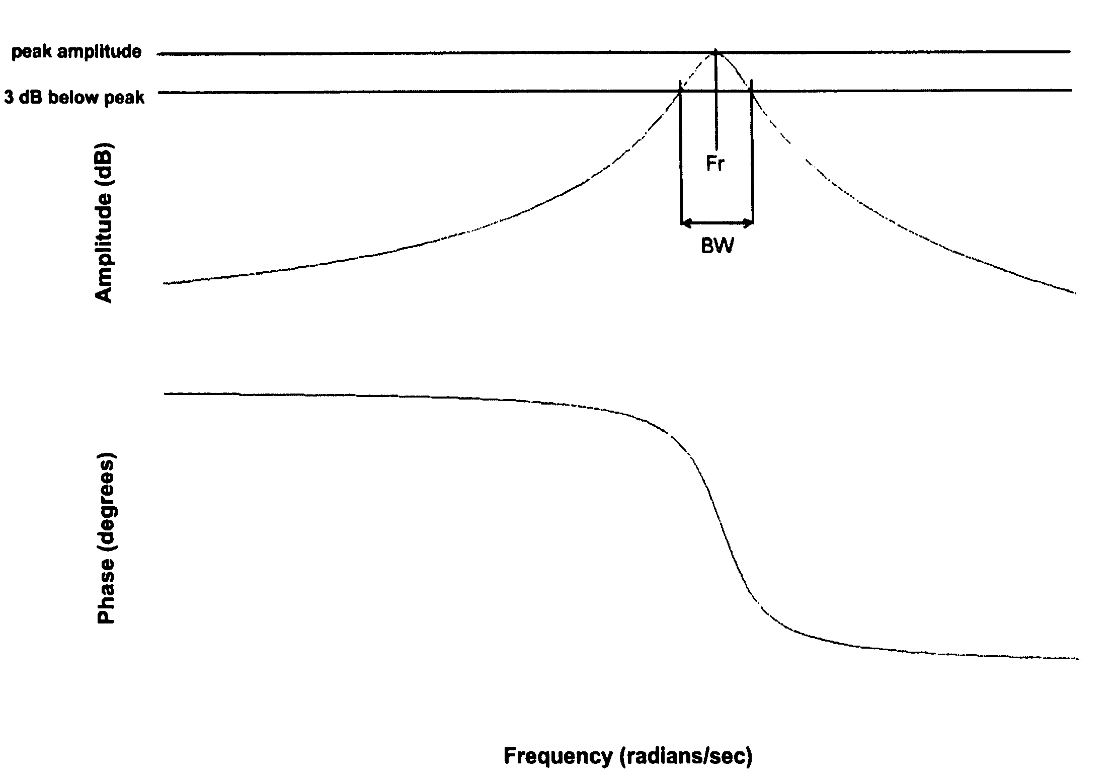
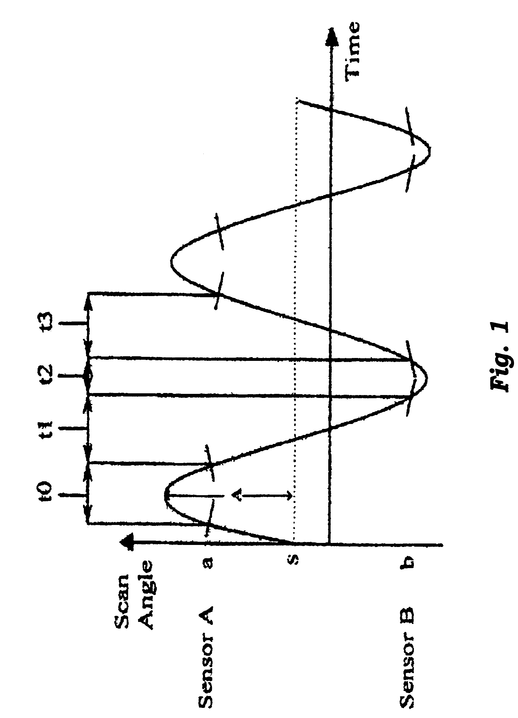
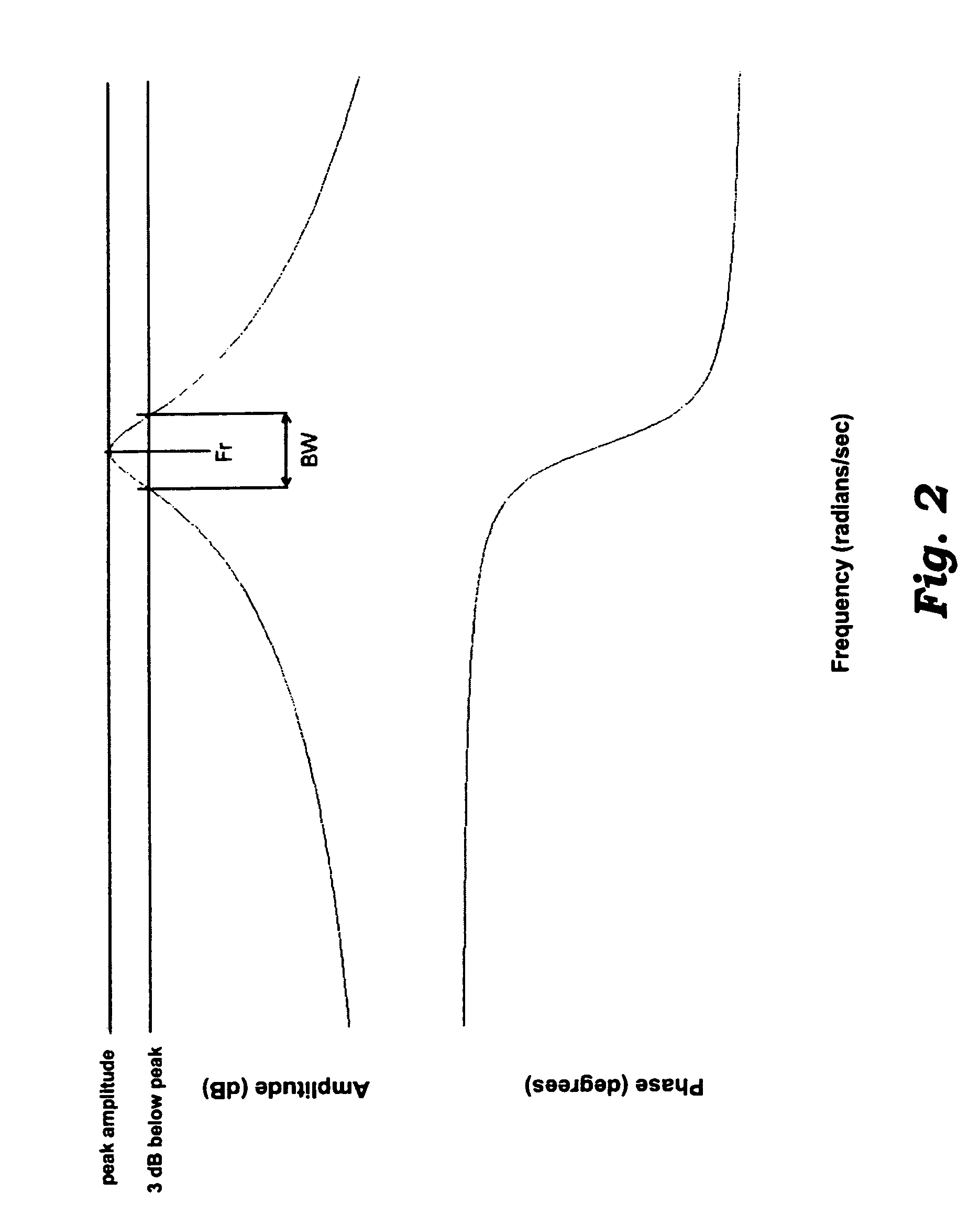
[0017]Generally, the motion of a torsion oscillator is controlled by characteristics of the electrical drive power supplied to it. The typical output scan angle versus time of laser light reflected from the mirrored surface of a torsion oscillator is depicted in FIG. 1....


PUM


Abstract

A method reduces the Q factor of the resonant frequency response of a torsional oscillator system in a laser printer, where the Q factor is expressed as a function of the resonant frequency and 3 dB bandwidth of the frequency response. The frequency response of the torsional oscillator system is a function of at least a rotational inertia, a spring constant and a damping constant. The method includes the steps of decreasing the rotational inertia of the torsional oscillator system by a first factor, and decreasing the spring constant by a second factor that is substantially equal to the first factor. The method generally increases component yields, thereby reducing component costs. Also, laser printers using torsion oscillators having reduced Q factors may be used over a wider speed range. Conversely, a single laser printer model may be used at a single speed, rather than at speeds that vary due to variations in resonant frequency. The method also provides for greater freedom of movement of the operating point of the printer during printer development.

Description

[0001]This application is a continuation-in-part of U.S. patent application Ser. No. 10 / 689,175, filed Oct. 20, 2003, now U.S. Pat. No. 6,794,794 entitled BI-DIRECTIONAL GALVONOMETRIC SCANNING AND IMAGING.BACKGROUND OF THE INVENTION[0002]The invention relates generally to optical systems used in laser printers. More particularly, the invention relates to adjusting the resonant characteristics of a torsion oscillator mirror.[0003]Torsion oscillators with a mirrored surface are used in laser printers to scan a laser beam bi-directionally across a laser printer drum. Generally, the scan angle of the mirrored surface of the torsion oscillator varies sinusoidally with respect to time. The reflective element, or mirror, of the torsion oscillator is typically attached by elastic members to a rigid supporting mount. The elastic members suspend the mirror while allowing it to rotate over a limited range along a single axis. The elastic members act as a torsional spring, and together with the...

Claims


Application Information

Patent Timeline
Patent Type & Authority Patents(United States)
IPC IPC(8): H01L41/08G02B26/10
CPCG02B7/008G02B26/105G02B26/085
Inventor KLEMENT, MARTIN CHRISTOPHERPAWLEY, DANIEL EUGENE
Owner LEXMARK INT INC
Why Eureka
Try Eureka