Adaptive interpolation for use in reducing signal spurs

a technology of adaptive interpolation and signal spurs, applied in the field of real-time oscilloscopes, can solve the problems of truncated sinc filter failing to reject an undesired frequency, affecting the use of the maximum theoretical available bandwidth,

Active Publication Date: 2007-12-04
TELEDYNE LECROY
View PDF28 Cites 23 Cited by
  • Summary
  • Abstract
  • Description
  • Claims
  • Application Information

AI Technical Summary

Benefits of technology

[0013]Apart from the small effect of “leakage” or “crosstalk”, which will be discussed below, the cancellation between the spurs that results from this process is intrinsically substantially perfect (again, to the level of precision of the instrument). This cancellation between the two spurs then leaves us with a generally simple linear and finite(non-zero) response at all frequencies.
[0015]With respect to the '075 application, the present invention achieves a number of benefits. Some changes simply related to the change of operation frequencies are first noted. Hardware employed by the DSO to implement the present invention preferably modifies diplexer (elements 29, 31, and 33), and filters (elements 34, 37) of FIG. 2 of the '075 application so that the crossover frequency is 5 GHz instead of 6 GHz (see FIG. 10 of the present application), and the diplexer does not have to have a very narrow crossover. In accordance with the present invention, element 53 of the '075 application is preferably removed, as the full frequency range receivable by the channel dedicated to high frequencies can be used. Element 30 of the '075 application is preferably removed, as the presence of a fLO signal is no longer a threat to performance. Rather its presence amounts to a shift of the DC level in the channel, which can be calibrated away. The design of the present invention does not need special equipment to generate, track or filter out fLO, thus preferably avoiding the need for elements 43, 44, 45, 46, 47, 48, 49, 50, 52, 54, 55, 56, 57, 58, 59, 60, 61, 62, and 63 of the '075 application. On the software front, many filters used in the “075 application (74, 75, 81, 82, 88) are preferably not needed, as the removal of various spurs is performed differently (i.e. without generic filters) in accordance with the invention. The generation of a software version of fLO is preferably not needed, justifying the preferred removal of elements 86 and 87 of the '075 application. The most notable changes comprise the preferred modification of elements 73 and 80, and thus the trivialization of elements 83 and 84, of the '075 application.

Problems solved by technology

Secondly, the inventor of the present application has recognized another phenomenon hindering the use of the maximum theoretical available bandwidth.
This phenomenon causes a problem even if all signals are received in the correct frequency channel.
But, when approaching the Nyquist limit (fS / 2), the truncated Sinc filter fails to reject an undesired frequency because it is just too close to the desired frequency, and both are part of a curve with a finite slope.

Method used


Image

  • Adaptive interpolation for use in reducing signal spurs
  • Adaptive interpolation for use in reducing signal spurs
  • Adaptive interpolation for use in reducing signal spurs

Examples


Embodiment Construction

[0035]The invention will now be described making reference to the accompanying drawings.

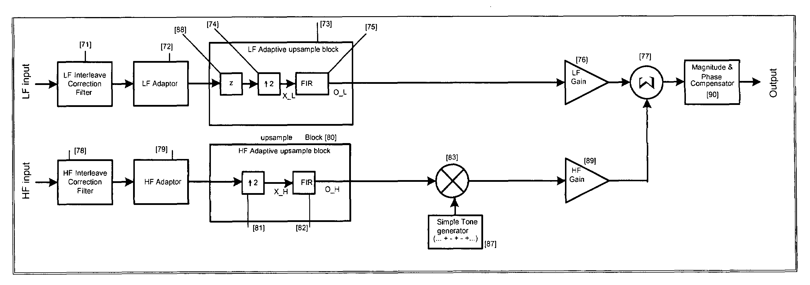
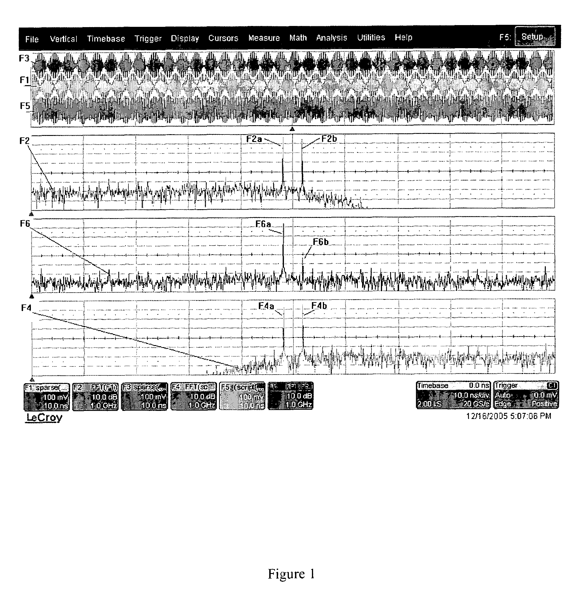
[0036]FIG. 1 depicts the functional results of the invention when applied to a DBI equipped oscilloscope. As is shown in FIG. 1, a signal F1 is received by the oscilloscope. Signal F1, of a frequency just below the Nyquist limit, is depicted as being received on a time domain scale for the horizontal axis. When this signal is acquired by a LF channel (see element 32 of FIG. 10 below), upsampled (see block 73 of FIG. 11 below) and fast-fourier transformed (FFT) into the frequency domain along the horizontal, a frequency spectrum F2 results. Note in F2, not only is a first peak F2a generated, a second, undesirable peak F2b is generated from the aforementioned interpolation near the Nyquist limit. Similarly, when the same input signal passes through the mixing and amplifying elements 33-45 and 50-52 of FIG. 10 below, a signal is acquired by a HF channel (see element 63 of FIG. 10 below), upsampled (...


PUM


Abstract

A method and apparatus for acquiring an analog signal. The method of the invention comprising the steps of acquiring a first portion of the analog signal by a first channel, the first portion of the analog signal spanning a first bandwidth range, and acquiring a second portion of the analog signal by a second channel, the second portion of the analog signal spanning a second bandwidth range adjacent the first bandwidth range. At least one spur in the signal acquired by the first channel corresponding to a portion of the analog signal that should have properly been acquired by the second channel is offset with an opposite spur in the second channel.

Description

BACKGROUND OF THE INVENTION[0001]The present invention is directed to real time oscilloscopes, and more particularly to real time oscilloscopes employing a bandwidth extension scheme (i.e. Digital Bandwidth Interleaving), such as that described in U.S. patent application Ser. No. 11 / 281,075, titled HIGH BANDWIDTH OSCILLOSCOPE, filed Nov. 17, 2005 (“the '075 application”), currently pending, the entire contents thereof being incorporated herein by reference. In accordance with the disclosure of this pending patent application, each of a plurality of channels (two, for example, which will be referred to as LF (low frequency) and HF(high frequency)) receive a portion of an input signal corresponding to a specific frequency band. As described in the above application, additional processing is performed on this split signal for acquiring and digitizing the signal. In accordance with the present invention, further modification to this process of the '075 application is presented.[0002]The...

Claims


Application Information

Patent Timeline
Patent Type & Authority Patents(United States)
IPC IPC(8): H03M1/12
CPCG01R13/0272
Inventor LAMARCHE, FRANCOIS
Owner TELEDYNE LECROY
Why Eureka
Try Eureka