
Optical element and wavelength separator using the same

a wavelength separator and optical element technology, applied in the field of optical elements, can solve the problems of difficult production of two- or three-dimensional photonic structures, and achieve the effects of high wavelength resolution, small size, and easy manufacturing

Inactive Publication Date: 2007-12-04
NIPPON SHEET GLASS CO LTD +1
View PDF8 Cites 1 Cited by
  • Summary
  • Abstract
  • Description
  • Claims
  • Application Information

AI Technical Summary

Benefits of technology

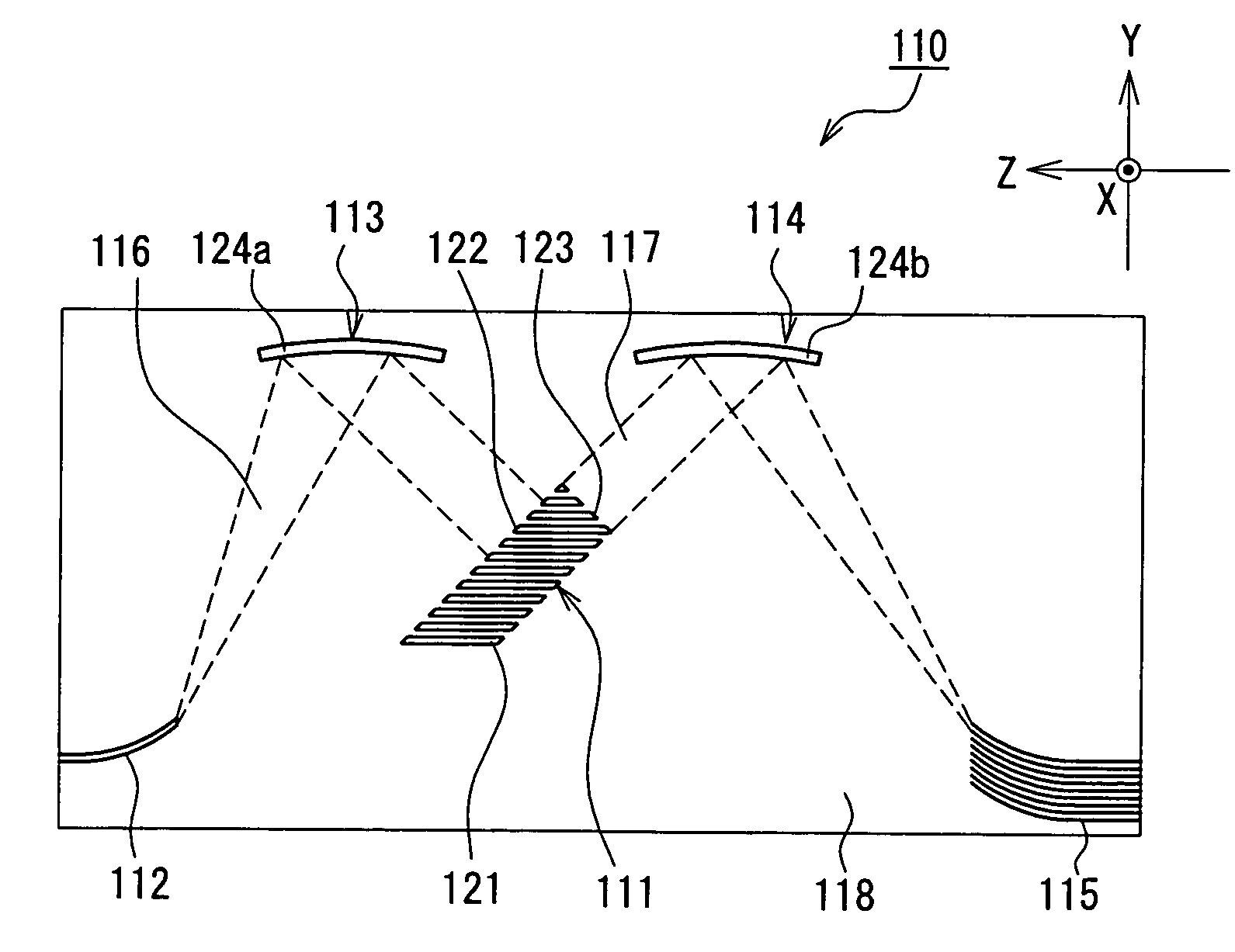
The present invention provides an optical element that is easy to manufacture, small in size, and has high wavelength resolution. Additionally, the invention provides a wavelength separator that uses this optical element. The optical element includes a one-dimensional photonic crystal structure with grooves in parallel with one another and an incident end face formed obliquely with respect to the direction in which the grooves extend, and an output end face formed approximately perpendicular to the incident end face. The wavelength separator includes the optical element and a light input section causing a light beam to be incident on the incident end face of the optical element, and a light output section on which light beams outgoing from the output end face of the optical element are incident, the light beams outgoing at different output angles depending on wavelengths thereof. The light input section causes the light beam incident on the incident end face from the light input section to enter the optical element through the incident end face in a manner such that the light beam is coupled with a photonic band within the second Brillouin zone exclusive of a boundary between the first and second Brillouin zones.

Problems solved by technology

However, two- or three-dimensional photonic structures are difficult to produce, since the structures have complexity.

Method used


Image

  • Optical element and wavelength separator using the same
  • Optical element and wavelength separator using the same
  • Optical element and wavelength separator using the same

Examples


embodiment 1

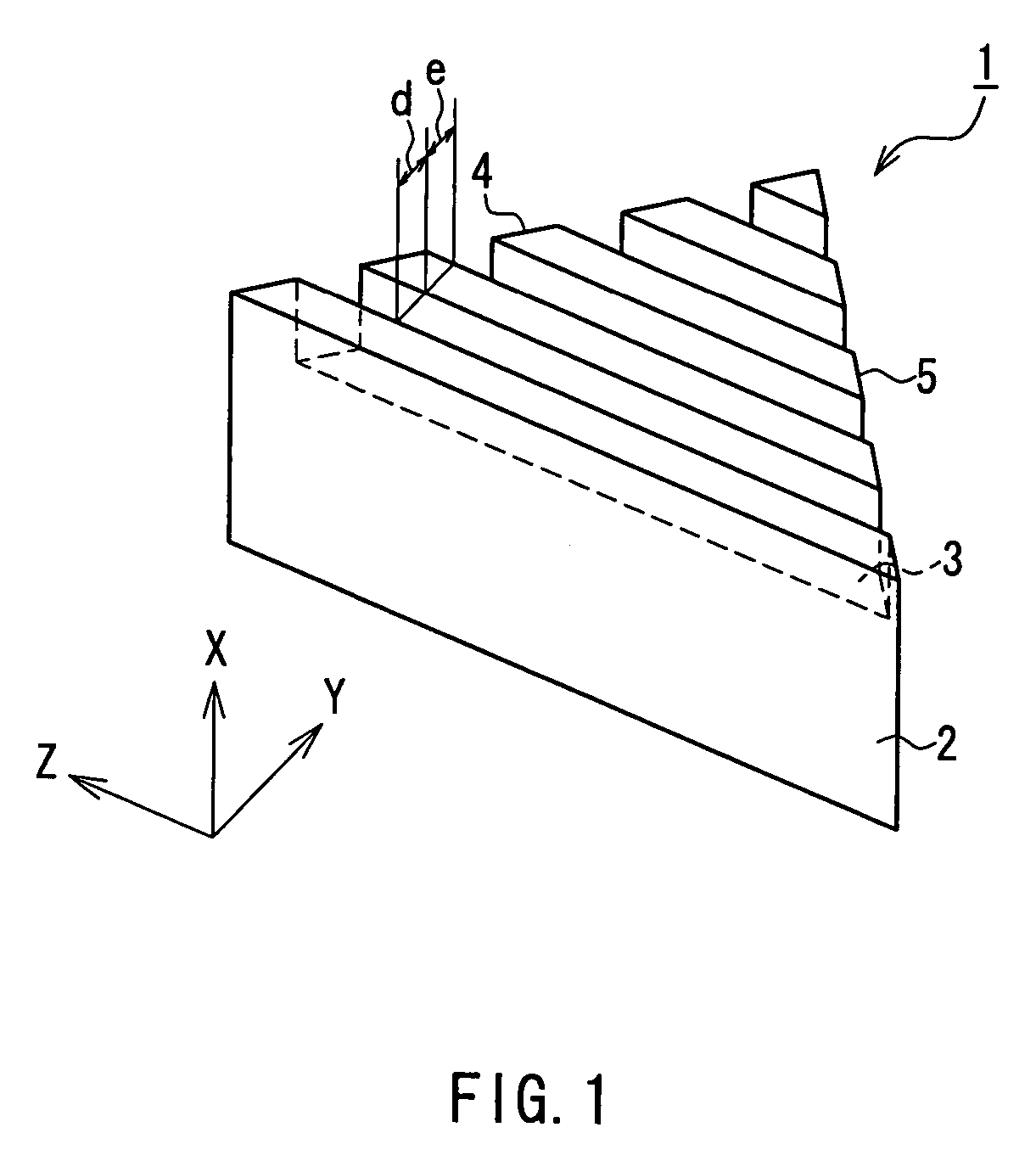
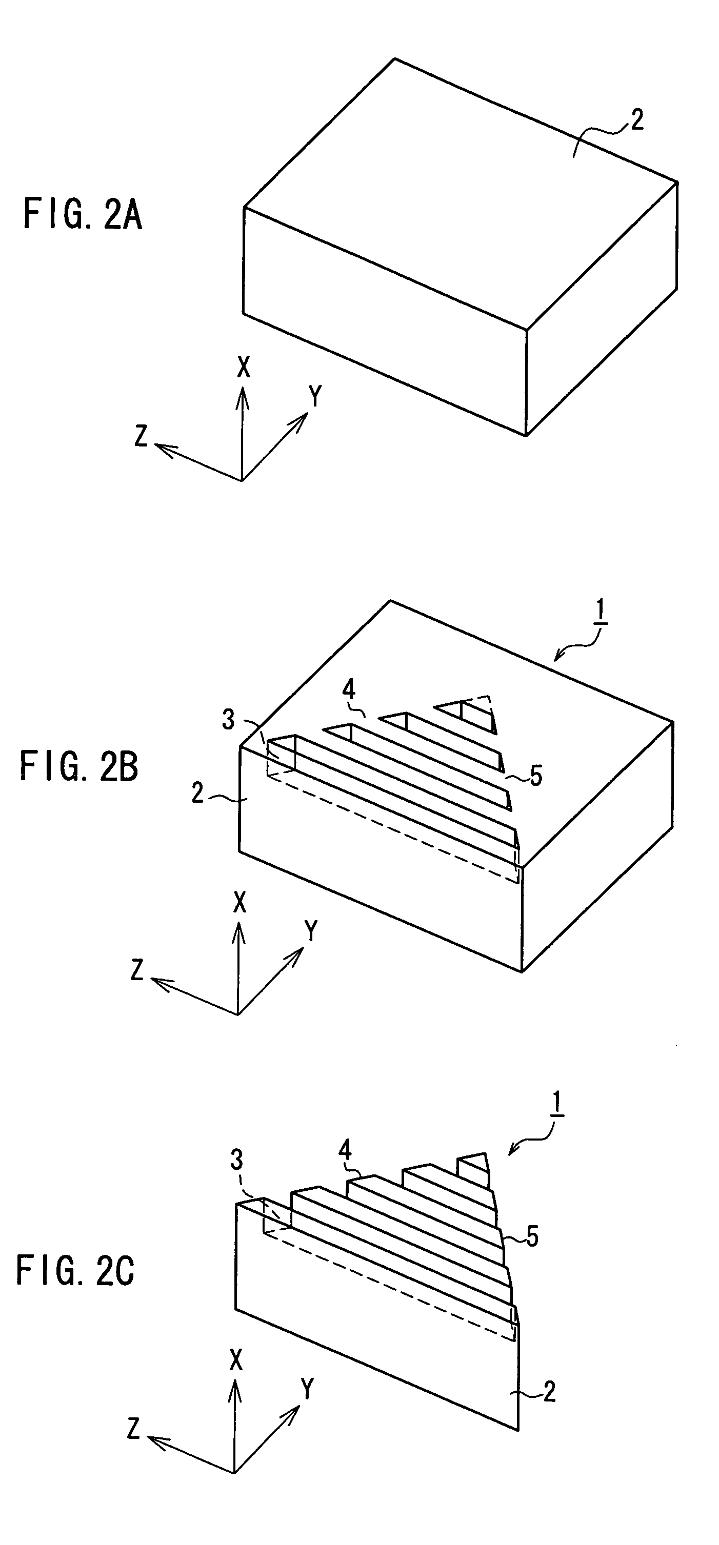
[0068]The following describes an optical element according to Embodiment 1 of the present invention. FIG. 1 is a perspective view illustrating a configuration of an optical element according to Embodiment 1 of the present invention. In FIG. 1, the optical element 1 is configured by forming grooves 3 in a homogeneous medium 2. The grooves 3 are formed in parallel so as to extend in one direction and have uniform widths. Intervals at which the grooves 3 are arranged also are uniform. It should be noted that, as shown in FIG. 1, the direction in which the grooves 3 extend is a Z-axis direction, a direction in which layers of the homogeneous medium 2 and air filling the grooves 3 are stacked is a Y-axis direction, and a direction perpendicular to both the Z axis and the Y axis is an X-axis direction. In other words, the grooves 3 are parallel with an X-Z plane, and are stacked in the Y-axis direction. Thus, the optical element 1 is configured so that air and the homogeneous medium 2 are...

example 1

[0096]The following describes Example 1 in which the propagation in the optical element 1a (see FIG. 3) according to Embodiment 1 was determined by simulation. The optical element 1a was a periodic structure in which a substance having a refractive index of 1.45 and a substance having a refractive index of 1.00 were provided alternately with uniform thicknesses. The structure had an incident end face 4 inclined through an angle ψ1 of 45° and a period a of 1000 (nm). The simulation was performed with an incident angle θ of an incident light beam 7 being fixed to 15°, and with a wavelength λ0 of the incident light beam 7 being varied from a / 0.460 to a / 0.485.

Resultant output angles φ of outgoing light beams corresponding to the foregoing respective wavelengths are shown in Table 1. It should be noted that the output angle φ is an angle formed between the Z-axis direction and the outgoing light beam.

[0097]

TABLE 1No.a / λ0Wave length λ0Output angle φ (deg)10.4602173.9143.520.4652150.5437.5...

example 2

[0100]The following describes Example 2 in which the propagation in the optical element 1a according to Embodiment 1 was determined by simulation. The optical element 1a was a periodic structure in which a substance having a refractive index of 1.45 and a substance having a refractive index of 1.00 were provided alternately with uniform thicknesses. The structure had an incident end face 4 inclined through an angle ψ1 of 50° and a period a of 1000 (nm). The simulation was performed with an incident angle θ of an incident light beam 7 being fixed to 35°, and with a wavelength λ0 of the incident light beam7 being varied from a / 0.420 to a / 0.450. Resultant output angles φ of outgoing light beams corresponding to the foregoing respective wavelengths are shown in Table 2.

[0101]

TABLE 2No.a / λ0Wave length λ0Output angle φ (deg)10.4202380.9537.520.4252352.9431.530.4302325.5827.540.4352298.8524.350.4402272.7321.260.4452247.1918.570.4502222.2214.0

[0102]As shown in Table 2, a change in the outpu...


PUM


Abstract

A wavelength separator includes a one-dimensional photonic crystal structure formed by providing a plurality of grooves in parallel with one another at uniform intervals in a homogeneous medium, and has an incident end face formed obliquely with respect to a direction in which the grooves extend, and an output end face formed approximately perpendicular to the incident end face.

Description

BACKGROUND OF THE INVENTION[0001]1. Field of the Invention[0002]The present invention relates to an optical element capable of separating light having different wavelengths, for use in optical communication, pickup apparatuses for use with optical disks, etc.[0003]2. Description of Related Art[0004]Due to the rapid spread of the Internet, there is a strong demand for an increase in the information transmission capacity of an optical fiber communication network. Under such a circumstance, wavelength division multiplexing (WDM) has been developed rapidly. The WDM is a communication technique of multiplexing independent information to transmit it, using light having a plurality of different wavelengths. According to this technique, in order to separate a signal that has been multiplexed, a wavelength separator having satisfactory wavelength selectivity is required.[0005]As an element to be used as such a wavelength separator, a photonic crystal has been proposed (see, for example, JP-A...

Claims


Application Information

Patent Timeline
Patent Type & Authority Patents(United States)
IPC IPC(8): G02B6/12G02B6/122G02B6/28G02B6/34
CPCB82Y20/00G02B6/1225G02B6/2931G02B6/2938G02B6/29328
Inventor OYA, KAZUAKINAKAZAWA, TATSUHIROKITTAKA, SHIGEOTSUNETOMO, KEIJINISHII, JUNJI
Owner NIPPON SHEET GLASS CO LTD
Learn More