[0008]The specification of the '353 patent explains that an “ . . .
advantage of the present invention is that it efficiently provides a highly controllable deeply placed bonded radial
interface layer within an optical preform providing for a smooth transition of one or more properties between two materials. The controlled properties may include . . . index of
refraction . . . ” The specification further emphasizes that, at least in most instances, and certainly the instances explained in any depth, the rotation of the preform during heating is about an axis orthogonal to any applied
gravitational field. Although the representative processes disclosed in the '353 may be effective in achieving the stated objectives, they are undoubtedly cumbersome. Moreover, the processes of the '353 are apparently performed prior to the heating and drawing of any fiber.
[0009]Accordingly, there exists a need for a simplified method of fabricating a GRIN
optical fiber in which the refractive-index-gradient profile is formed during the heating and vertical drawing of a core rod and a cladding tube, whether it be during the drawing of a
single fiber or during the heating and drawing of a plurality of bundled fibers in order to fabricate a fused bundle comprising a plurality of GRIN optical fibers.SUMMARY
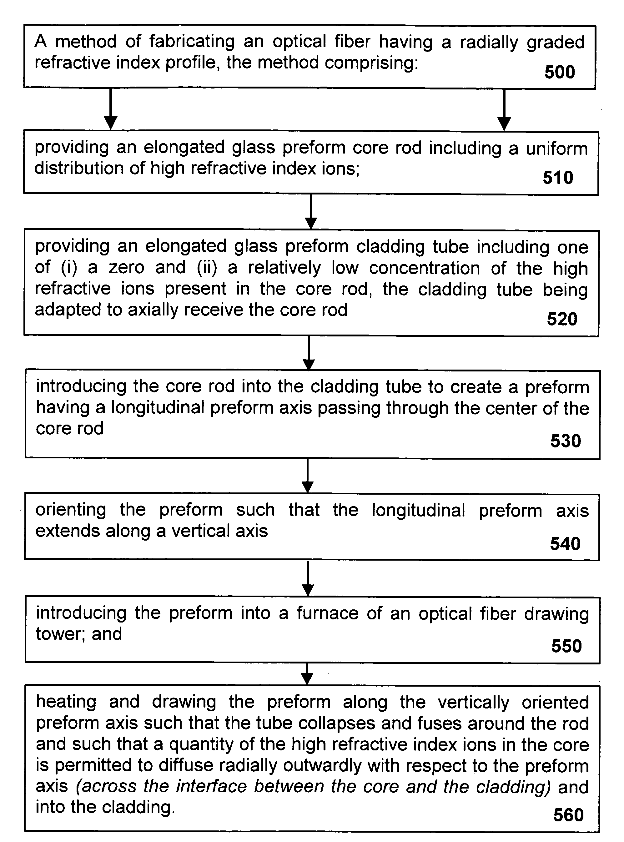
[0010]In accordance with a typical implementation, a method of fabricating an optical fiber having a radially graded
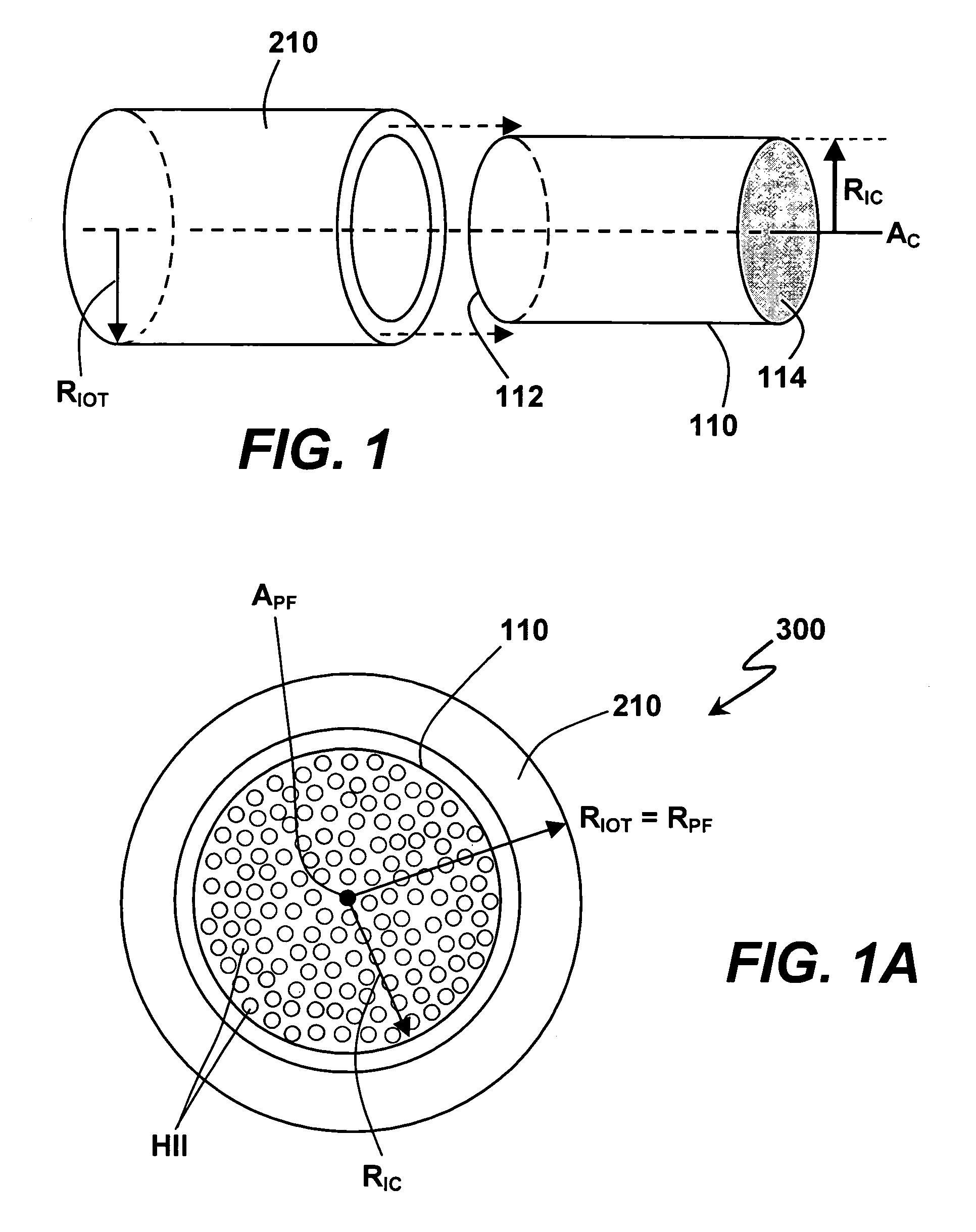
refractive index includes the steps of (1) providing an elongated glass core rod containing a concentration of high
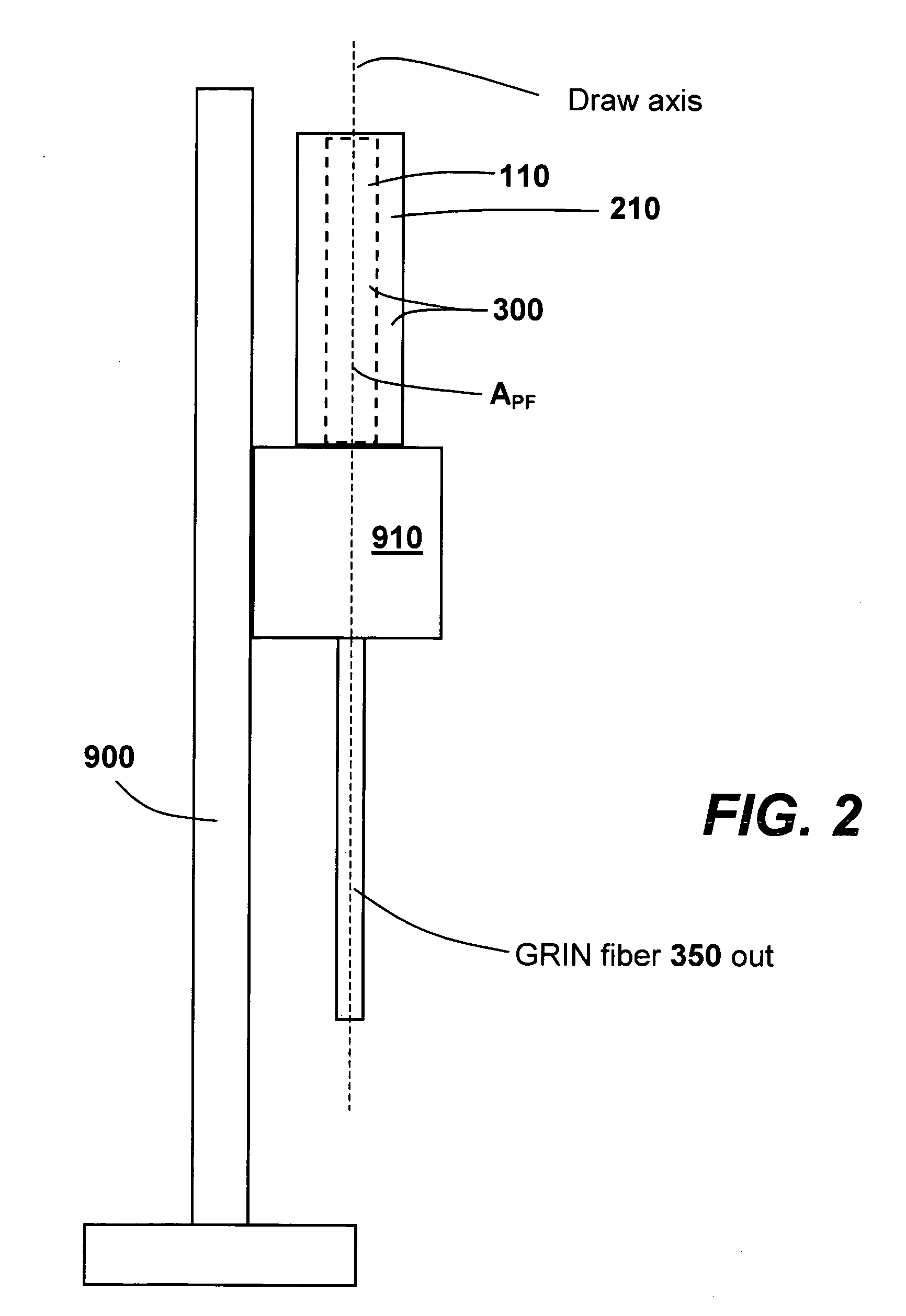
refractive index ions; (2) providing an elongated glass cladding tube containing one of (i) a zero and (ii) a relatively low concentration of the high refractive ions present in the core rod, the cladding tube being adapted to axially receive the core rod; (3) introducing the core rod axially into the cladding tube to create a preform having a longitudinal preform axis passing through the center of the core rod; (4) orienting the preform such that the longitudinal preform axis extends along a
vertical axis; (5) introducing the preform into a furnace of an optical
fiber drawing tower; and (6) heating and drawing, simultaneously, the preform along the vertically oriented preform axis such that, as a result of simultaneous heating and drawing, each of (i) the tube collapses and fuses around the rod and (ii) a quantity of the high refractive index ions originating in the core rod diffuses radially outwardly with respect to the preform axis and into the cladding material. It is to be understood that, in various alternative implementations, a first simultaneous heating and drawing step may be performed in order to collapse the tube about the core and that at least one subsequent step in which the core and cladding are simultaneously heated and drawn is undertaken in order to effectuate outward
ion diffusion. It is also to be understood that, in various alternative implementations, a cladding tube containing one of (i) a zero and (ii) a relatively low concentration of the high refractive ions present in the core rod means, in either case, a cladding tube containing a much lower concentration of high-refractive-index ions than the concentration in the core rod. That is, while in many implementations, a cladding tube having a zero concentration of high-refractive-index ions is ideal, the practicality of achieving a zero concentration may be difficult at best. Accordingly, situations in which a zero concentration is ideal, but in which a zero concentration may be difficult to achieve, are envisioned as being within the scope of the language “a relatively low concentration of the high refractive ions present in the core rod.” The concentration is “low” relative to the concentration in the core rod. An alternative, but equivalent way of stating the same desired condition is that, in various implementations, the concentration within the cladding tube of the high-refractive-index ions present in the core rod is as low as practicable. A large migration (e.g.,
diffusion) of high-refractive-index ions from the core rod into the cladding tube during heating and drawing is facilitated by rendering the concentrations of high-refractive-index ions in the core rod and the cladding tube as disparate as practicable in view of all parameters applicable to a specific implementation, including, for instance, the maximum desired refractive index at the axis of the core rod.
[0011]Implementations of the present invention facilitate the fabrication of a graded refractive index optical fiber in accordance with
fiber drawing processes corresponding to the conventional rod-in-tube method used for creating traditional optical fibers characterized by a sharply defined change in refractive index between the core and the cladding. Various implementations of the present invention obviate the need for the fabrication of an intermediate preform in which, for example, a tube is collapsed about a core rod by heating and rolling about the core rod axis. In accordance with implementations of the present invention, the
radius of the fiber resulting from the heating and drawing step is reduced relative to the outer
diameter of the cladding tube in a manner analogous to the processes for extruding traditional optical fibers.
[0012]In various implementations, GRIN optical fibers may be drawn, bundled and then redrawn to fabricate flexible and fused optical components comprising plural GRIN optical fiber elements. Moreover, in some such implementations, the redrawing of each GRIN fiber as part of a component comprising multiple GRIN fibers enhances the gradient of each GRIN fiber of a selected set of GRIN fibers. That is, a predetermined gradient profile of a particular fiber within the bundle may not be achieved until the final draw in a multi-draw process.
[0013]In another set of implementations, multiple constituent-GRIN-fiber pre-forms in each of which, for example, the cladding tube is collapsed around or otherwise secured about a cladding rod are bound together and drawn through a furnace such that the individual fibers of the multi-fiber preform are not GRIN fibers, but emerge from the furnace as constituent GRIN fibers in a multi-GRIN-fiber component (e.g., a fused bundle).


