
Method for operating an internal combustion engine

a technology of internal combustion engine and combustion chamber, which is applied in the direction of machines/engines, electric control, instruments, etc., can solve the problems of favorable influence of emissions and fuel consumption

Inactive Publication Date: 2007-12-11
ROBERT BOSCH GMBH
View PDF9 Cites 2 Cited by
  • Summary
  • Abstract
  • Description
  • Claims
  • Application Information

AI Technical Summary

Benefits of technology

The present invention provides a method for analyzing the quality of a structure-borne noise sensor over its lifetime by quantifying its drift. This allows for the replacement of the sensor at a later service call, reducing operating costs. The method uses a reference signal, which is detected or ascertained in a new sensor or a reference engine. The change in the reference signal over time indicates the drift of the sensor. The method is advantageous for cylinder diagnosis as it rules out drift of the sensor as the cause for an unusual signal. The method is accurate, cost-effective, and improves the quality of information provided by the sensor.

Problems solved by technology

Finally, emissions and fuel consumption are favorably affected.

Method used


Image

  • Method for operating an internal combustion engine
  • Method for operating an internal combustion engine
  • Method for operating an internal combustion engine

Examples


Embodiment Construction

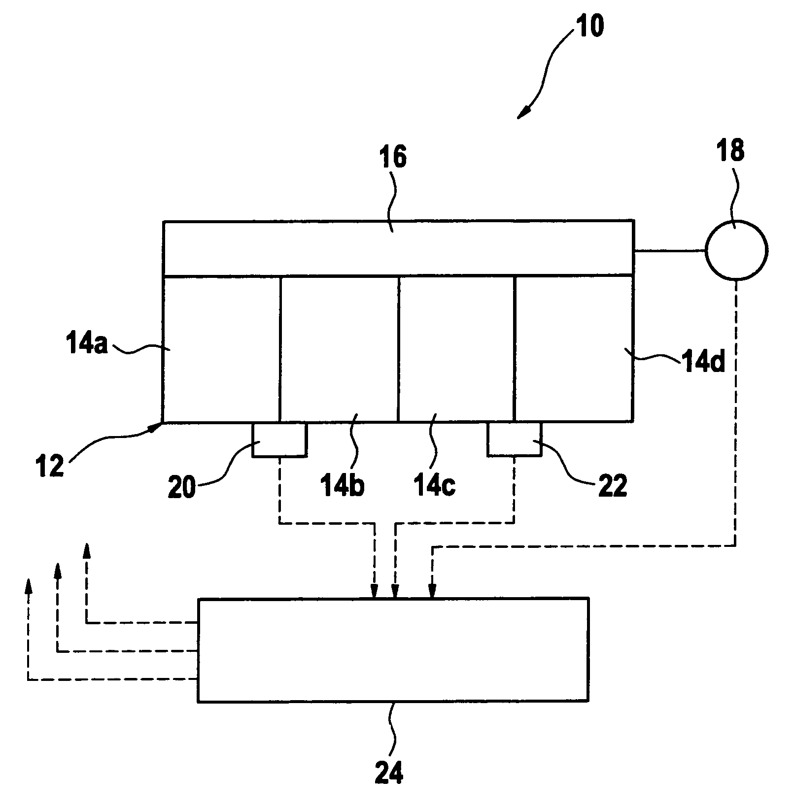
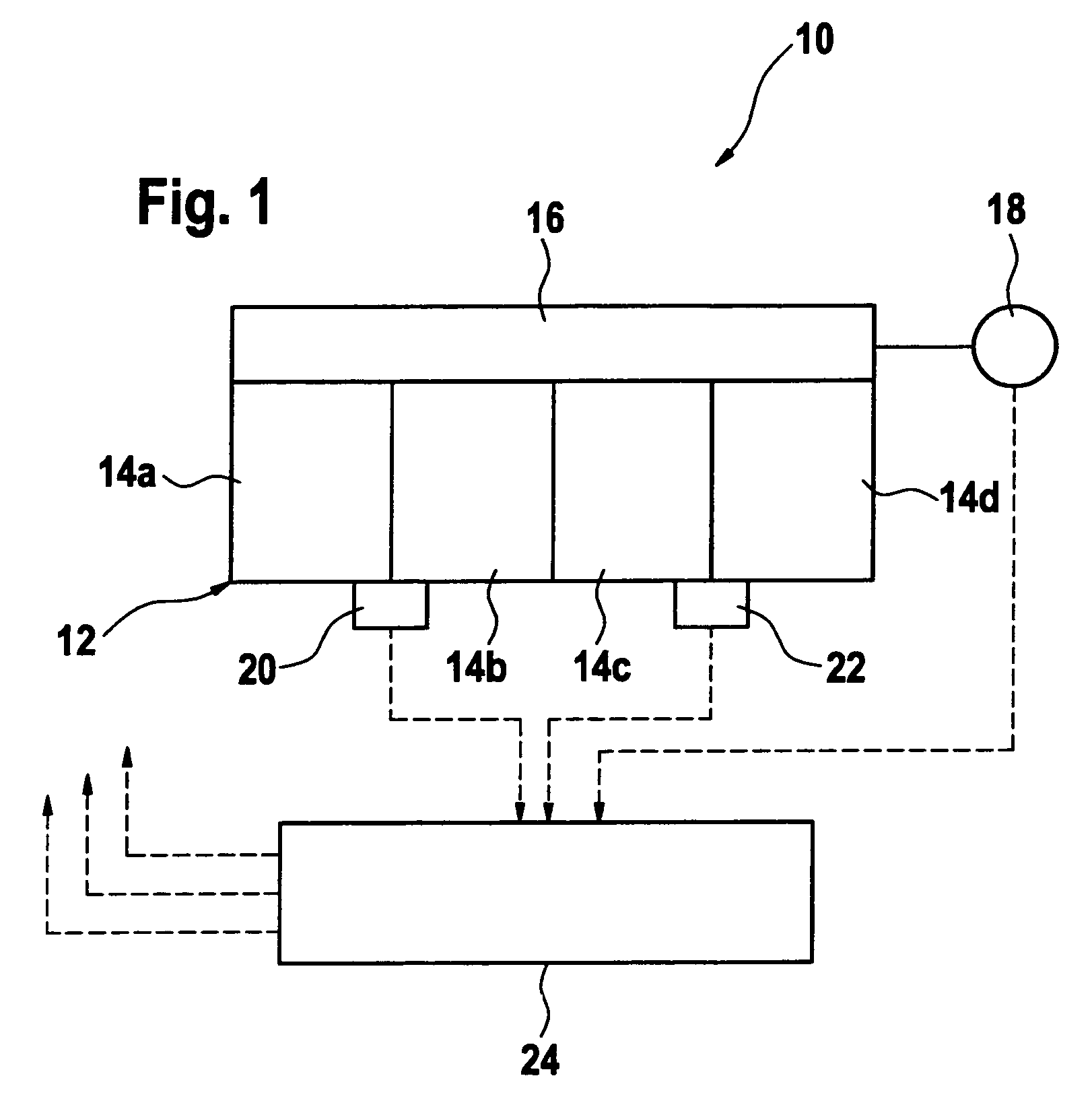
[0022]An internal combustion engine is labeled overall with reference numeral 10 in FIG. 1. It is used for the propulsion of a motor vehicle, not depicted in FIG. 1, and operates by the diesel principle. There are four in-line combustion chambers 14a, 14b, 14c, and 14d in an engine block 12. As is known, a crankshaft 16 is set into rotation when engine 10 is operated, and its rotational speed and angular position are detected by a sensor 18.

[0023]A first structure-borne noise sensor 20 is situated on engine block 12 in the middle between combustion chambers 14a and 14b. A second structure-borne noise sensor 22 is situated on engine block 12 in the middle between combustion chambers 14c and 14d. The signals of sensors 18, 20, and 22 are supplied to a control and / or regulating unit 24, which controls and / or regulates the operation of engine 10.

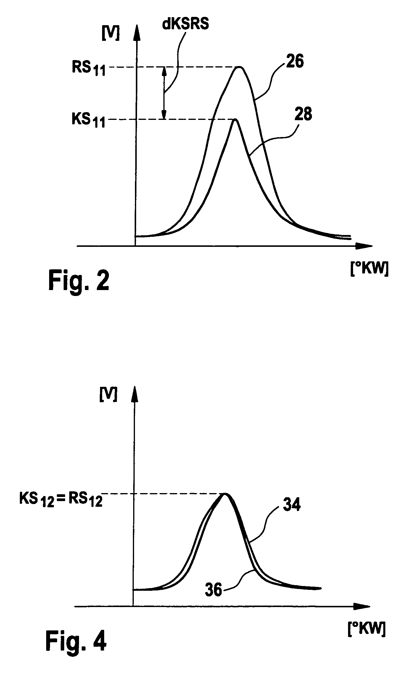
[0024]In order to recognize, quantify, and compensate a drift of the signal of first structure-borne noise sensor 20, for example, a procedure ...


PUM


Abstract

In an internal combustion engine, a structure-borne noise generated in a combustion chamber is detected by a structure-borne noise sensor. A quantity is ascertained on the basis of the structure-borne noise signal. A reference quantity of an undrifted structure-borne noise sensor is ascertained for a certain reference operating state for the combustion chamber, during continuous operation of the engine the quantity is ascertained for the reference operating state, and from a change over time of the ascertained quantity with respect to the reference quantity, a drift of the structure-borne noise sensor is ascertained.

Description

FIELD OF THE INVENTION[0001]The present invention relates to a method for operating an internal combustion engine in which a structure-borne noise generated by a pressure change in a combustion chamber is detected by a structure-borne noise sensor and a quantity is ascertained on the basis of the structure-borne noise signal.BACKGROUND INFORMATION[0002]The use of signals of one or more structure-borne noise sensors for analyzing the combustion process in the combustion chambers of an internal combustion engine is described, for example, in German Patent Application No. DE 198 45 232. These structure-borne noise sensors have the advantage compared to a direct pressure measurement in the combustion chambers using pressure sensors that they are considerably less expensive and their installation is relatively simple. The pressure variation in the combustion chambers is recognizable mainly by an analysis of the low-frequency component of the structure-borne noise signal. This low-frequen...

Claims


Application Information

Patent Timeline
Patent Type & Authority Patents(United States)
IPC IPC(8): G01M15/00G01M99/00
CPCF02B77/085F02D41/222F02D41/2474G01M15/08G01M15/12F02D41/123Y02T10/40F02D2400/08F02D2200/025
Inventor SCHUELER, MATTHIASMADER, CHRISTIANYOUSSEF, MOHAMEDHUGEL, CHRISTIAN
Owner ROBERT BOSCH GMBH
Learn More