Sensor module unit and a throttle apparatus equipped with the sensor module unit

a sensor module and module technology, applied in the direction of electric control, instruments, machines/engines, etc., can solve the problems of reducing operational efficiency, complex operation for installing these sensors individually, and affecting the operation of the sensor module unit, so as to facilitate the plurality installation and eliminate the limitation of the size and shape of the apparatus

Active Publication Date: 2007-12-11
MIKUNI CORP
View PDF9 Cites 3 Cited by
  • Summary
  • Abstract
  • Description
  • Claims
  • Application Information

AI Technical Summary

Benefits of technology

[0017]The throttle position sensor is a non-contact type position sensor such as a Hall element or MR element to detect an opening angle of the throttle valve. A need is thus eliminated for complicated installation and adjustment operation of the throttle position sensor.
[0021]In the sensor module unit according to the present invention, when the unit main body is installed in the vicinity of the throttle axle of the intake throttle apparatus, each of a plurality of sensors is positioned in a predetermined measuring position in the throttle apparatus, whereby it is possible to remarkably facilitate installation of the plurality of sensors arranged on an inlet pipe side of an engine, thereby achieve positioning of each of the sensors in an accurate measuring position, and eliminate limitations on size and shape of an apparatus targeted for installation of the sensors.

Problems solved by technology

Such an adjustment needs to be performed for each throttle body in a case of a multi-cylinder engine, and an assembling operation becomes extremely complicated.
Further, it is necessary to install a plurality of sensors such as an intake-air temperature sensor and intake-air pressure sensor besides the TPS on an inlet pipe side of the engine, and operation for installing these sensors individually is complicated and reduces operational efficiency.
However, in the sensor integrated throttle body as described in Patent Document JP H09-250374, since the throttle body itself serves as sensor mounting structure on which a plurality of sensors are mounted, there are provided large limitations on size of the throttle apparatus and internal and external shapes of the throttle body, and production cost is thus increased.
Further, since each sensor is installed individually to a predetermined portion of the throttle body, installation operational efficiency is not improved greatly in a production process as compared to a conventional sensor installation method.
Further, in a method of installing an ECU substrate, on which a plurality of sensors are mounted, in a throttle body as disclosed in Patent Document JP H11-294216, the method contributes to reduction in operation of wiring between the sensors and ECU substrate, but imposes large limitations not only on size of the throttle apparatus and internal and external shapes of the throttle body, but also on size of the ECU substrate and arrangement positions of electric components on the substrate.
Therefore, particularly, it is sometimes difficult to mount such a substrate on a small-size throttle apparatus for a two-wheel motorcycle or compact-sized car.

Method used


Image

  • Sensor module unit and a throttle apparatus equipped with the sensor module unit
  • Sensor module unit and a throttle apparatus equipped with the sensor module unit
  • Sensor module unit and a throttle apparatus equipped with the sensor module unit

Examples


first embodiment

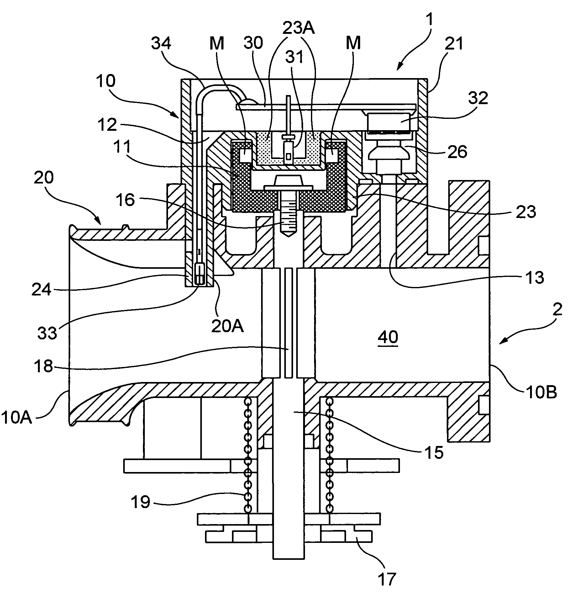
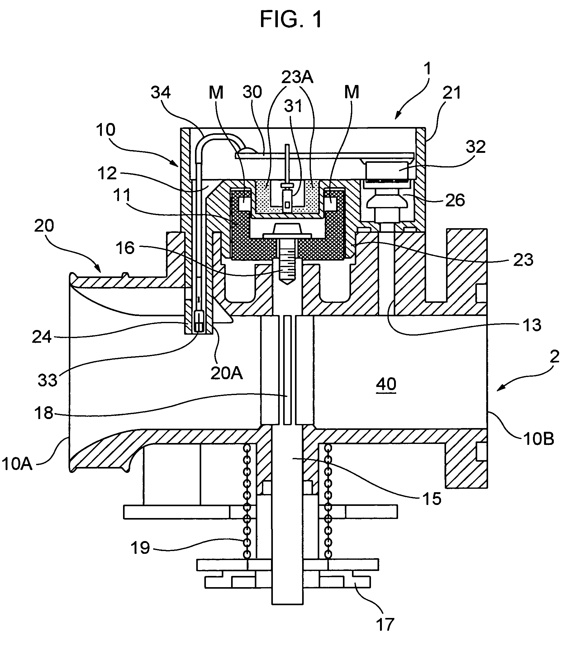
[0045]FIG. 2 shows a first embodiment of the sensor module unit according to the present invention as shown in FIG. 1.

[0046]The sensor module unit according to the first embodiment has three sensors, intake-air temperature sensor 33, TPS 31, and intake-air pressure sensor 32.

[0047]Therefore, the sensor module unit is provided with intake-air temperature sensor holding portion 24 installed with the intake-air temperature sensor, TPS holding portion 23A and intake-air pressure sensor holding portion 26 in respective predetermined positions in the unit main body 10.

[0048]Herein, the intake-air temperature sensor holding portion 24 is comprised of a conduit projecting to reach the inner wall of the throttle body 20 of the intake throttle apparatus 2 (FIG. 1), and the conduit is engaged in the opening 20A provided in the throttle body 20, whereby positioning in the vicinity of the throttle axle is performed when the unit main body 10 is installed in the intake throttle apparatus 2. At th...

second embodiment

[0051]FIG. 3 shows a second embodiment of the sensor module unit according to the present invention.

[0052]The sensor module unit according to the second embodiment has four sensors, intake-air temperature sensor 33, TPS 31, intake-air pressure sensor 32, and outside-air pressure sensor 35.

[0053]Therefore, the sensor module unit is provided with intake-air temperature sensor holding portion 24 installed with the intake-air temperature sensor, TPS holding portion 23A, intake-air pressure sensor holding portion 26 and outside-air pressure sensor holding portion 36 in respective predetermined positions in unit main body 10.

[0054]Herein, the outside-air pressure sensor 35 is installed so that a sensor surface faces upward to detect air pressure outside the unit main body 10.

[0055]In addition, in the same way as in the first embodiment as described above, the intake-air temperature sensor holding portion 24 is comprised of a conduit projecting to reach the inner wall of the throttle body ...

third embodiment

[0058]FIG. 4 shows a third embodiment of the sensor module unit according to the present invention.

[0059]The sensor module unit according to the third embodiment has two sensors, intake-air temperature sensor 33 and TPS 31.

[0060]Therefore, the sensor module unit is provided with intake-air temperature sensor holding portion 24 installed with the intake-air temperature sensor and TPS holding portion 23A in respective predetermined positions in unit main body 10.

[0061]In addition, in the same way as in the first and second embodiments as described above, the intake-air temperature sensor holding portion 24 is comprised of a conduit projecting to reach the inner wall of the throttle body 20 of the intake throttle apparatus 2 (FIG. 1), and the conduit is engaged in the opening 20A provided in the throttle body 20, whereby positioning in the vicinity of the throttle axle is performed when the unit main body 10 is installed in the intake throttle apparatus 2. At the same time, the intake-...


PUM


Abstract

The present invention provides a sensor installation structure for installation of a plurality of sensors disposed on an inlet pipe side of an engine, and enables each of the sensors to be positioned in an accurate measuring position. A sensor module unit is integrally provided with a plurality of sensors necessary for fuel supply control and intake-air flow rate control in an internal-combustion engine, and has an intake-air temperature sensor holding portion installed with an intake-air temperature sensor, at least one of a throttle position sensor holding portion installed with a position sensor to detect an opening angle of a throttle valve in an intake throttle apparatus, and an intake-air pressure sensor holding portion installed with an intake-air pressure sensor, and a unit main body that integrally accommodates the intake-air temperature sensor holding portion, and the at least one of the throttle position sensor holding portion and the intake-air pressure sensor holding portion to position these holding portions in respective predetermined arrangement positions in the unit, whereby each of the sensors is positioned in a predetermined measuring position in the throttle apparatus when the unit main body is installed in the vicinity of a throttle axle of the intake throttle apparatus.

Description

TECHNICAL FIELD OF THE INVENTION[0001]The present invention relates to a structure for installing sensors to detect various kinds of data indispensable to fuel supply control and intake-air flow rate control of an internal-combustion engine.BACKGROUND ART[0002]In recent years, it has become common that an internal-combustion engine (hereinafter, referred to as an “engine” as appropriate) of a vehicle including at least a large-size motorcycle is controlled by an electronic control apparatus provided with a computer.[0003]In the electronic control apparatus of the engine, various kinds of sensors to always detect an operational state and intake-air state of the engine are disposed in the engine and its peripheral apparatuses, and an ECU (Electronic Control Unit) that performs electronic concentrated engine control performs optimal control of the engine based on a variety of data sent from the various kinds of sensors.[0004]In the engine, fuel such as gasoline and air are mixed, and t...

Claims


Application Information

Patent Timeline
Patent Type & Authority Patents(United States)
IPC IPC(8): F02D9/02F02D9/10F16K37/00G01M99/00
CPCF02D9/105F02D11/10F16K37/005F16K37/0041F02D41/187F02D2009/0294F02D2200/0406F02D2200/0414F02D2200/0404F02D35/00F02D9/00
Inventor MUSASHI, KAZUHIROYAMAZAKI, SHIGERU
Owner MIKUNI CORP
Why Eureka
Try Eureka