
Device and method for percutaneous placement of lumbar pedicle screws and connecting rods

a technology of connecting rods and screws, applied in the field of instruments, can solve the problems of significant morbidity and mortality of lumbar fusion procedures, complex surgical interventions, and blood loss, and achieve the effects of reducing the cost, facilitating the surgical procedure, and high precision of positioning the guid

Inactive Publication Date: 2007-12-11
THEKEN SPINE
View PDF45 Cites 378 Cited by
  • Summary
  • Abstract
  • Description
  • Claims
  • Application Information

AI Technical Summary

Benefits of technology

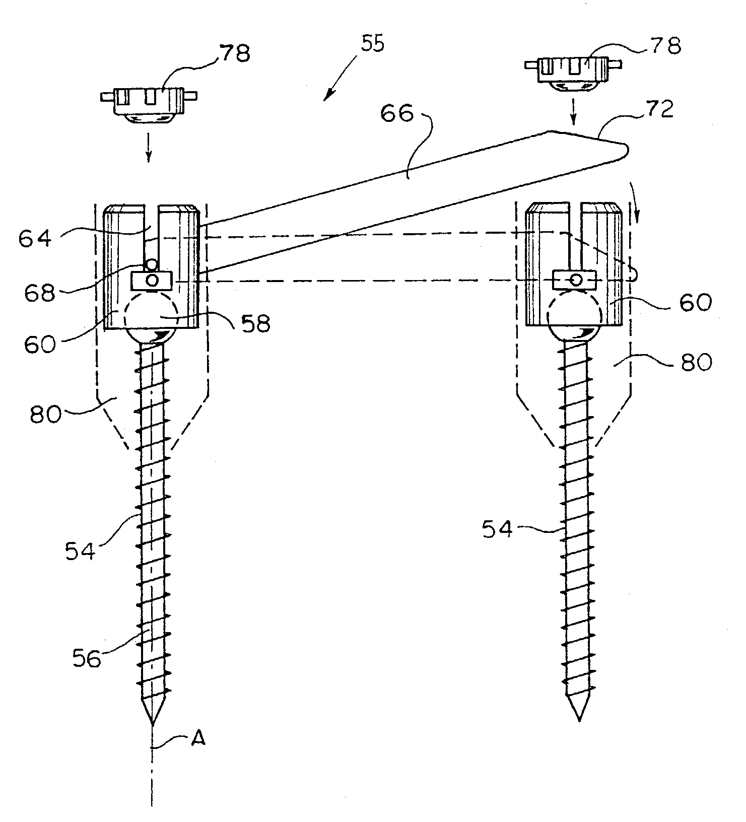
[0012]In contrast to the known prior art methods, in which the connecting rod is introduced below and above the screws and guided through soft tissues parallel to the spine, the inventive system allows the surgeon to guide the connecting rod towards one of the screws vertically. Therefore, one of the advantages of the inventive method is that penetration through soft tissues is localized, and, as a consequence, the cut soft tissues are only minimally disturbed.
[0013]A further aspect of the invention relates to a guide system for subcutaneously placing the screws in the pedicles to be interlinked. Configuration of the inventive guide system allows a surgeon to guide and position the screws so that coupling and displacement of the connecting rod between its primary and final positions is performed in a simple and reliable manner. Thus, a time-consuming and onerous alignment procedure, including displacement of the connecting rod through the holes of the screw heads, is significantly simplified. Accordingly, the safety of the inventive method is increased.
[0015]In accordance with still another aspect, the inventive system further includes an identification system configured to landmark the pedicles to be interlinked in a manner utilizing multiple imaging techniques. In accordance with still another aspect of the invention, the inventive system includes a placement system for directing and automatically placing the screw placing instruments in the desired position. The placement system is configured to allow a guide, providing the screws and screw placing instruments with the desired trajectory, to move in three mutually perpendicular planes relative to the landmarks. Accordingly, the operating surgeon is able to achieve high precision of positioning the guide relative to the identified entry points to the pedicles.
[0016]According to another aspect of the invention, there is an orthopedic / neurosurgical kit including a combination of instruments, which are used during the performance of the inventive method. The kit providing the surgeon with a ready to be used assembly of guides, screws and screw placement instruments associated with the inventive method greatly facilitates the surgical procedure and, thus, reduces its cost.
[0017]It is, therefore, an object of the invention to provide a minimally-invasive surgical procedure for interlinking vertebra that avoids injury to tissues not otherwise involved in this procedure.

Problems solved by technology

This involves a significant, complex surgical intervention, with massive dissection of the paravertebral musculature.
As a consequence, the classic lumbar fusion procedure is associated with significant morbidity, including blood loss, increased anesthesia time with its attendant complications, and increased risk of infection.
Additionally, quite often the patient experiences significant postoperative pain requiring longer hospital stay which adds substantial cost to the current systems.
The cost of such equipment can be prohibitively high which limits the use of this procedure to a few medical facilities.
Still another undesirable consequence of the endoscopic procedure is its complexity, requiring considerable experience of a medical staff capable of using this equipment to properly place the screws as well as a staff of highly trained technicians.
Hence, the procedure is associated with additional requirements imposed upon a surgeon, an increase in overall surgery time and, as a consequence, additional health risks for the patient.
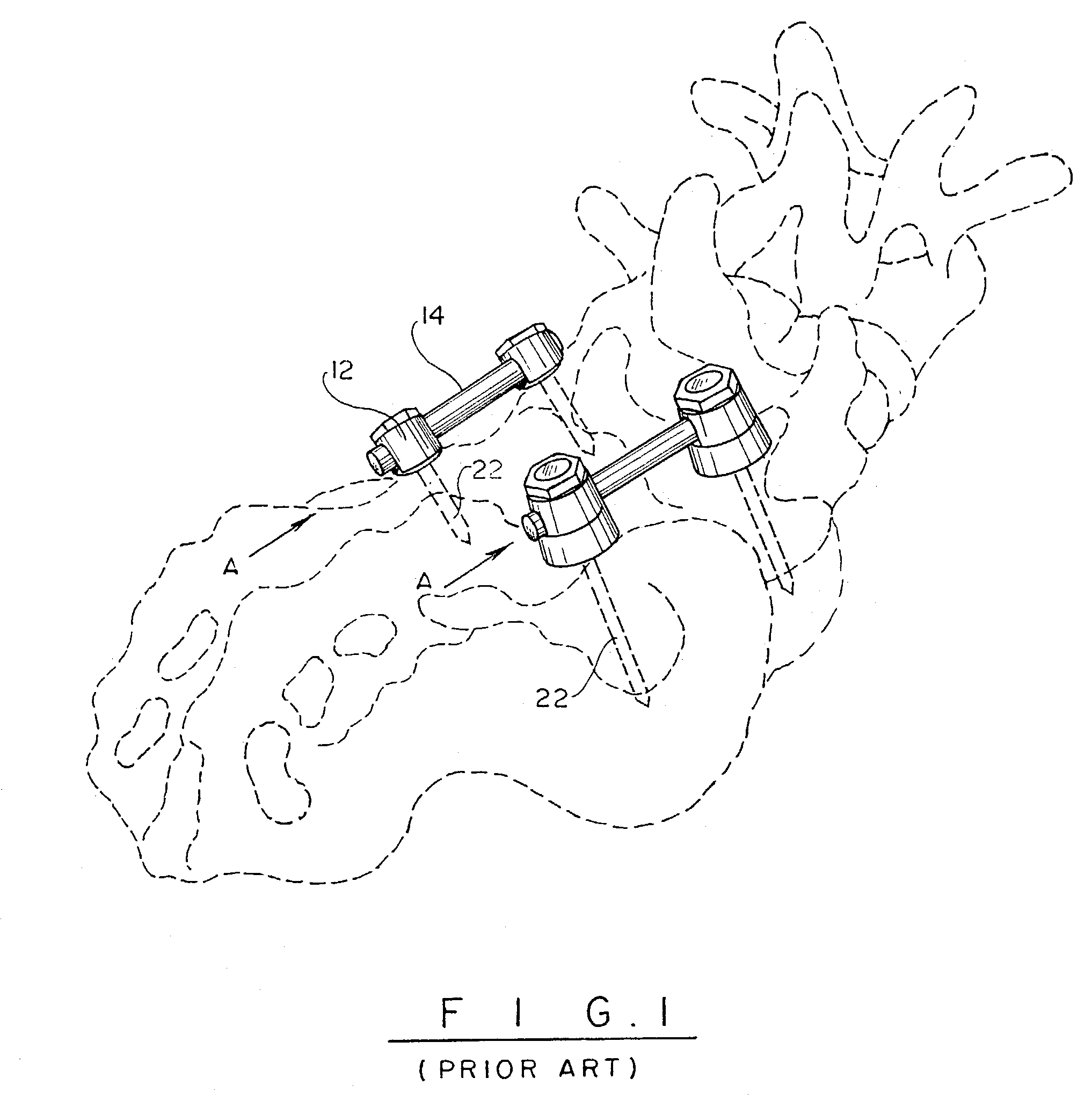
Yet another problem associated with the above discussed system is the issue of passing bone screws into the pedicles of the lumbar spine in such a fashion that with merely the use of surface anatomy, in conjunction with intraoperative imaging, the screws can be secured into the pedicles with maximum purchase of bone and minimum risk of injury to peri-pedicular structures, such as nerve roots.

Method used


Image

  • Device and method for percutaneous placement of lumbar pedicle screws and connecting rods
  • Device and method for percutaneous placement of lumbar pedicle screws and connecting rods
  • Device and method for percutaneous placement of lumbar pedicle screws and connecting rods

Examples


Embodiment Construction

[0041]As illustrated in FIGS. 3–4, the inventive method is performed to interlink vertebra to be fused by percutaneously guiding a connecting rod 66 in alignment with a longitudinal A-A axis of a screw 54 and, upon coupling the connecting rod 66 with this screw, pivoting the rod 66 so that it bridges adjacent screws 54. Accordingly, a pathway formed for one of the adjacent screws 54, which is advanced along this pathway towards the pedicle of one of the vertebra to be fused, is subsequently traversed by the connecting rod 66 that, thus, is automatically aligned with and engages a screw head 60 of the one screw 54.

[0042]Inventive system 55, configured to assist the surgeon to perform the inventive method, in addition to the screws 54 and the connecting rod 66, includes nuts 78 securing leading 70 (FIG. 4) and trailing 72 ends of the connecting rod 66 after the pedicle screws have been positioned relative to one another. Vertical displacement of the rod 66 requires that the screw head...


PUM


Abstract

A minimally invasive method for stabilizing adjacent vertebrae to be fused is accomplished with a device configured to interlink the pedicles of the adjacent vertebrae and including multiple pedicle screws. Each of the pedicle screws has a screw head configured to receive a connecting rod in a position, in which the rod and the receiving pedicle screw are vertically aligned.

Description

CROSS REFERENCE TO RELATED APPLICATION[0001]This application is based on and claims priority to a U.S. Provisional Application No. 60 / 405,261 filed on Aug. 21, 2002 and fully incorporated herein by referenceBACKGROUND OF THE INVENTION[0002]1. Field of the Invention[0003]The present invention relates to an instrumentation system, and method for operating the same, used in fusion procedures of the spine. In particular, the invention relates to an instrumentation system for subcutaneously interlocking pedicles of adjacent vertebra to be fused and to a minimally-invasive posterior-approach method of interlocking the pedicles.[0004]2. Background of the Related Prior Art[0005]Over the past twenty years, the value of pedicle screw stabilization in enhancing fusion procedures of the lumbar spine has been proven unambiguously. Many systems have been introduced to achieve this, and presently, numerous systems exist for the placement of screws and connecting rod or plate systems as a component...

Claims


Application Information

Patent Timeline
Patent Type & Authority Patents(United States)
IPC IPC(8): A61B17/56A61F2/30A61B17/17A61B17/32A61B17/70A61B17/88A61B17/90
CPCA61B17/1757A61B17/7002A61B17/7005A61B17/7037A61B17/7085A61B17/7032A61B17/7004A61B2017/90A61B2017/32004A61B2017/3445A61B17/90
Inventor BOEHM, JR., FRANK H.MEINICK, BENEDETTA D.
Owner THEKEN SPINE
Learn More