Primary side controlled switching regulator

a switching regulator and side control technology, applied in the field of switching regulators, can solve the problems of poor load regulation at light load and no load, high power consumption caused, leakage inductor, etc., and achieve the effect of improving efficiency and reducing emi

Active Publication Date: 2007-12-18
SEMICON COMPONENTS IND LLC
View PDF6 Cites 80 Cited by
  • Summary
  • Abstract
  • Description
  • Claims
  • Application Information

AI Technical Summary

Benefits of technology

[0013]A switching regulator includes a transformer having a primary winding and an auxiliary winding. The primary winding is coupled to a positive supply rail. The auxiliary winding is coupled to a negative supply rail. A switch is connected in series with the primary winding and the auxiliary winding for switching the transformer. A current sense device is connected from the switch to the auxiliary winding for generating a current signal in accordance with a switching current of the transformer. A control circuit is coupled to the switch and the auxiliary winding of the transformer to generate a switching signal in response to the current signal. The switching signal is used for switching the switch and regulating the output of the switching regulator. A supplied capacitor is connected to the control circuit to supply the power to the control circuit. The auxiliary winding has a leakage inductor to store a stored energy when the switch is on. A diode is coupled from the negative supply rail to the supplied capacitor. The stored energy of the leakage inductor is discharged to the supplied capacitor through the diode once the switch is off. The connection of the transformer and the switch improves the efficiency and reduces the EMI.

Problems solved by technology

One disadvantage is high power consumption caused by the leakage inductor of the transformer 10.
Another disadvantage of this switching regulator is a poor load regulation at light load and no load.
One principal drawback of this prior-art invention is high EMI (electric and magnetic interference).

Method used


Image

  • Primary side controlled switching regulator
  • Primary side controlled switching regulator
  • Primary side controlled switching regulator

Examples


Embodiment Construction

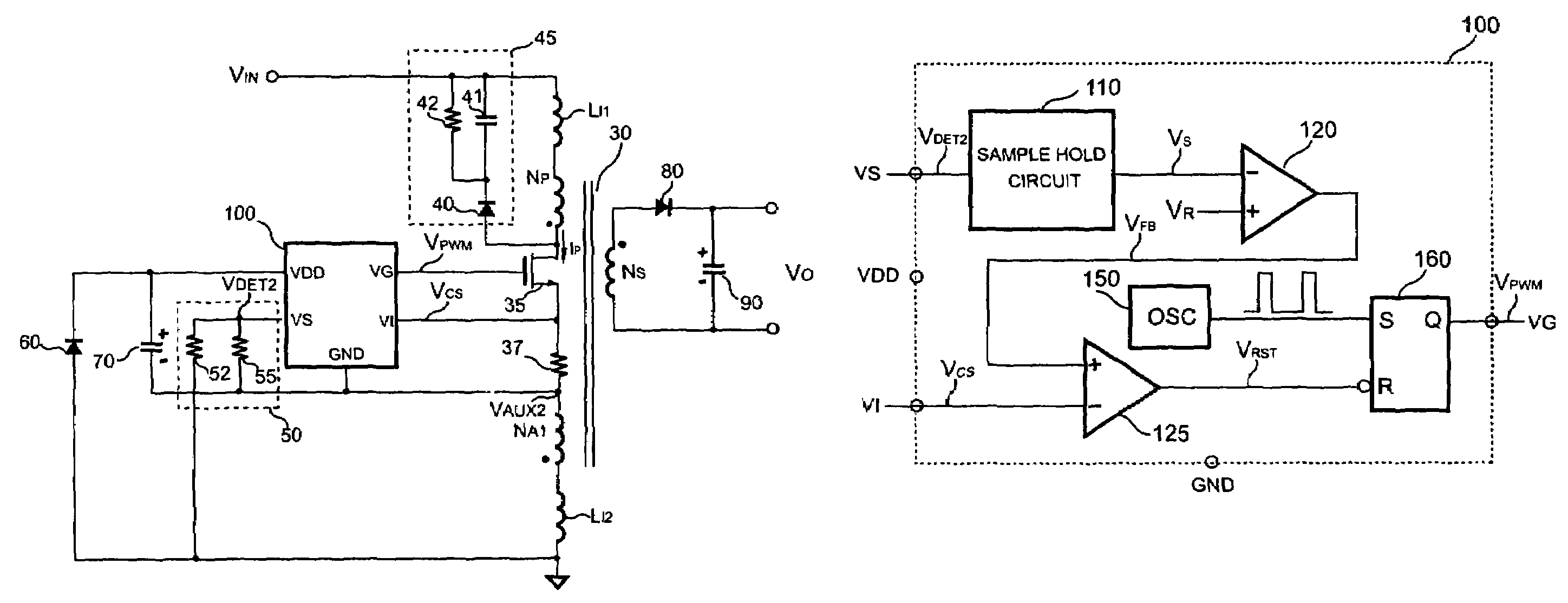
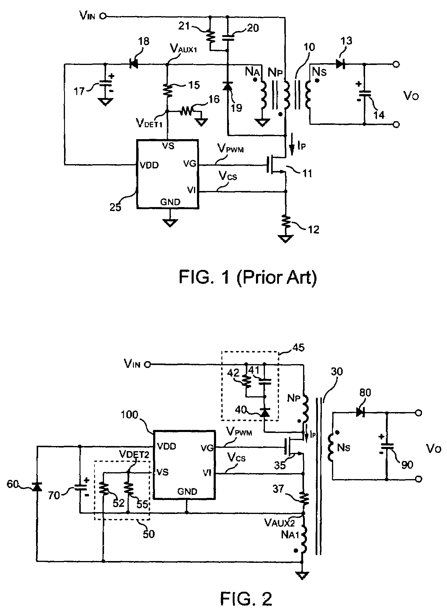
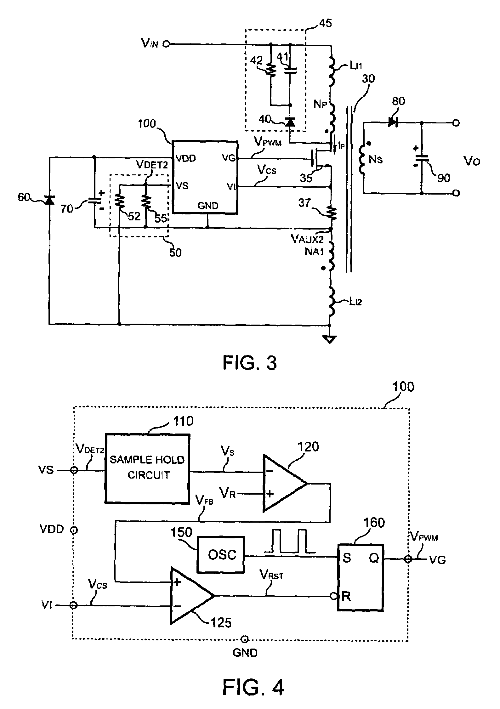
[0022]FIG. 2 shows a circuit diagram of a primary-side controlled switching regulator in accordance with the present invention. The switching regulator includes a transformer 30 for transferring a stored energy from a primary side of the transformer 30 to a secondary side of the transformer 30. The primary side of the transformer 30 has a primary winding NP and a first auxiliary winding NA1. The secondary side of the transformer 30 has a secondary winding NS. The primary winding NP and the first auxiliary winding NA1 are coupled to the supply rail of the transformer 30. The primary winding NP is coupled to a positive supply rail VIN of the supply rail of the transformer 30. The first auxiliary winding NA1 is coupled to a negative supply rail (ground) of the supply rail of the transformer 30. A switch 35 is connected in series with the primary winding NP and the first auxiliary winding NA1 for switching the transformer 30. The switch 35 can be a power transistor or a power MOSFET. Be...


PUM


Abstract

A switching regulator includes a transformer having a primary winding and an auxiliary winding connected to the supply rail of the switching regulator. The primary winding is coupled to the positive supply rail. The auxiliary winding is coupled to the negative supply rail. A switch is connected in series with the primary winding and the auxiliary winding for switching the transformer. A control circuit is coupled to the switch and the auxiliary winding to generate a switching signal for switching the switch and regulating the output of the switching regulator. A supplied capacitor is connected to the control circuit to supply the power to the control circuit. The auxiliary winding having a leakage inductor stores a stored energy when the switch is on. A diode is coupled from the negative supply rail to the supplied capacitor. The stored energy of the leakage inductor is discharged to the supplied capacitor through the diode once the switch is off. The connection of the transformer and the switch improves the efficiency and reduces the EMI.

Description

BACKGROUND OF THE INVENTION[0001]1. Field of the Invention[0002]The present invention relates to a regulator, and more specifically relates to a switching regulator.[0003]2. Description of Related Art[0004]Switching regulators are widely used to provide regulated voltage and current. Considerable ongoing research is focused on making regulators more efficient for saving power. A switching regulator typically includes a control circuit, a switch and a transformer. The control circuit is applied to sense the output voltage and / or the output current of the switching regulator, and generate a control signal to control the switch and regulate the output voltage and / or the output current of the switching regulator.[0005]FIG. 1 shows a circuit diagram of a traditional switching regulator. The traditional switching regulator includes a transformer 10 having a primary winding NP, a secondary winding NS and an auxiliary winding NA. A terminal of the primary winding NP is coupled to a positive...

Claims


Application Information

Patent Timeline
Patent Type & Authority Patents(United States)
IPC IPC(8): H02M3/335
CPCH02M1/44H02M3/335H02M2001/0006H02M1/0006
Inventor YANG, TA-YUNGCHENG, PEI-HSUAN
Owner SEMICON COMPONENTS IND LLC
Why Eureka
Try Eureka