
Numerically controlled drive device with device for detecting operating anomalies intended for detecting accidental collisions and method of detecting operating anomalies for this device

a technology of driving device and operating anomaly, which is applied in the direction of programme control, transmission, instruments, etc., can solve the problems of limiting the detection threshold to a rigid model, requiring motor speed feedback loops, and never theless remaining a complex and expensive solution, etc., and achieves a small detection threshold

Inactive Publication Date: 2007-12-18
CHARMILLES TECH SA
View PDF12 Cites 2 Cited by
  • Summary
  • Abstract
  • Description
  • Claims
  • Application Information

AI Technical Summary

Benefits of technology

"The present invention provides a detection device for accidental collisions on numerically controlled drive devices. The device comprises means of measuring position and means of analyzing error signals to detect collisions. The device is designed to have a lower detection threshold and is simple and cost-effective. The device can detect collisions along a path with high reliability and can also detect other causes of errors. The detection device can be used in various industrial applications such as manufacturing and logistical systems."

Problems solved by technology

The drawback of this modeling procedure is the need to ascertain the kinematics of all the objects in the work zone, this information being unavailable for example in regard to a machine tool for the offcuts that could get jammed between the workpiece and the tool.
In order to make up for this lack of knowledge regarding the location of bodies in the workspace, recourse has been had for example to vision systems, this nevertheless remaining a complex and expensive solution.
However, the use of an electric touch sensor requires the presence of electrically conducting objects.
The procedures described in this patent are restricted to drives with a rigid or very precise transmission, which require mechanical solutions that are needlessly expensive in the case of certain industrial applications for which the introduction of a second rule position sensor makes it possible to implement software procedures for compensating for errors related in particular to flexibility or to homokinetic defects.
This compensation may give rise to taxing demands on the motor speed feedback loop, as well as to large speed tracking errors and so to large variations in the motor current.
Thus, the raw signals, such as proposed in U.S. Pat. No. 5,119,006 no longer contain the relevant information making it possible to identify a collision with sufficient sensitivity to avoid waste.
However, the method proposed in this U.S. Pat. No. 5,304,906 is limited to a rigid model for the transmission of the drive.
The procedure is thus insufficient for drives for which the flexibility of transmission and the homokinetic defects assume considerable significance.
Moreover, the knowledge of the parameters such as the inertia and the torque constant of the motor is incompatible with numerous applications such as machine tools where the mass to be driven may easily vary by a factor of 5 during normal use of the installation.
The problem with this error signal relating to position between motor and driven part is that it is marred by homokinetic errors, which are characteristic of normal operation and again lead to the triggering limit being fixed at an excessive value.
On the other hand, the solution advocated is unsuitable when it is necessary to violently accelerate large inertias.

Method used


Image

  • Numerically controlled drive device with device for detecting operating anomalies intended for detecting accidental collisions and method of detecting operating anomalies for this device
  • Numerically controlled drive device with device for detecting operating anomalies intended for detecting accidental collisions and method of detecting operating anomalies for this device
  • Numerically controlled drive device with device for detecting operating anomalies intended for detecting accidental collisions and method of detecting operating anomalies for this device

Examples


Embodiment Construction

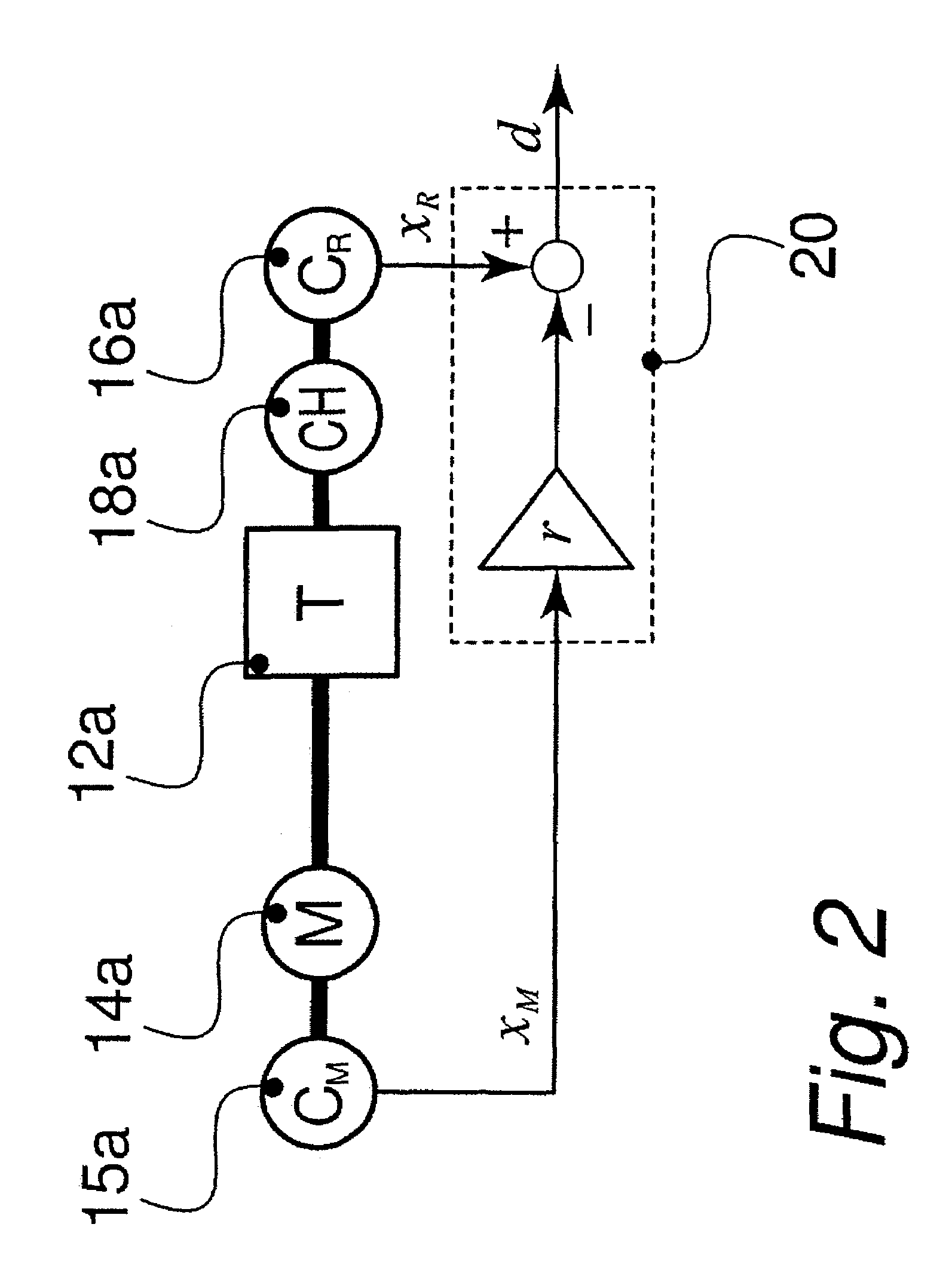
[0058]The numerically controlled drive device of the present invention possesses a general configuration such as illustrated in FIG. 2. The motor 14a is associated with a first position sensor 15a providing a first value of position xM and constituting first means of measuring position disposed upstream of a transmission assembly 12a through which the motion is transferred to the load 18a which is moved along a path. The position of the load 18a is measured by virtue of a second position sensor 16a providing a second value of position xR.

[0059]Means of calculation, in the form of a calculation unit 20, are devised so as to calculate at predetermined time intervals an error signal d according to the equation

d=xR−rXM

where r is equal to the reduction ratio of the transmission assembly 12a.

[0060]The error signal d therefore corresponds to the deviation between the position of the load and the motor position in relation to the load.

[0061]In the configuration illustrated in FIG. 1, the e...


PUM


Abstract

A drive device for a load (18a) comprises a device for detecting accidental collisions with a motor (14a), a first, respectively a second position sensor (15a, 16a) disposed upstream, respectively downstream of a transmission assembly (12a) providing first and second values of position. A calculation unit (20) makes it possible to calculate an error signal (d) corresponding to the difference of these position values. Ways to discriminate are devised so as to analyze the successive error signals as a function of the path (xR) traversed by the load in a spatial reference frame (xR, d). Filters with rectangular spatial window or with exponential spatial window are particularly adapted for discriminating between errors due to an accidental collision and those due to other causes attributable to normal operation. One thus obtains particularly reliable and sensitive collision detection with a very low detection threshold.

Description

BACKGROUND OF THE INVENTION[0001]The present invention relates to a numerically controlled drive device comprising a device for detecting operating anomalies intended for detecting accidental collisions, comprising:[0002]at least one motor able to drive a load along at least one path by way of an assembly of transmission elements,[0003]first means of measuring position disposed upstream of at least one of the elements of the said assembly for transmission to the motor and intended to provide a first value of position,[0004]second means of measuring position disposed downstream of this element of the assembly for transmission to said load and intended to provide a second value of position corresponding to the position of the load on said path,[0005]means of calculation for establishing at predetermined intervals error signals corresponding to the difference of the first and second values of position, and[0006]means of analysis for analyzing these error signals so as to detect acciden...

Claims


Application Information

Patent Timeline
Patent Type & Authority Patents(United States)
IPC IPC(8): G05B19/18G06F17/50G05B19/4061G05B19/19G05B19/4062
CPCG05B19/4061G05B19/4062G05B2219/37297Y02T10/82G05B2219/37626G05B2219/42272G05B2219/37625
Inventor ALTPETER, FRIEDHELM
Owner CHARMILLES TECH SA
Learn More