Transverse flux machine with stator made of e-shaped laminates

a technology of transverse flux and stator, which is applied in the direction of synchronous motors, magnetic circuit rotating parts, magnetic circuit shape/form/construction, etc., can solve the problems of long flux path of machine, high cost and difficulty in manufacture, and achieve the effect of more torqu

Inactive Publication Date: 2007-12-25
ROCHE DIAGNOSTICS GMBH +1
View PDF23 Cites 19 Cited by
  • Summary
  • Abstract
  • Description
  • Claims
  • Application Information

AI Technical Summary

Benefits of technology

[0013]In an embodiment the endings of the legs are tilted increasing the gaps between the rotor and the endings of the legs. Thereby the air-gap flux is modified / optimised making the air-gap surface larger between the rotor yoke and the legs. This means less current is needed to magnetise the E-core and more torque can therefore be produced.
[0014]In a preferred embodiment the middle leg is wider than the two outer legs, preferably twice as wide. This has proven to be an advantageous embodiment.

Problems solved by technology

The PMTFM is well known for its high torque per weight ratio, but it is quite expensive and very difficult to manufacture because many parts are required.
Although the SRM has some good characteristics, it is not widely used mainly because of the high investment required to develop machines for an application and the high volume production and sales needed to lower the per unit cost of this development.
This machine has the disadvantage of long flux-paths in the stator yoke 15 from stator pole to stator pole and though the rotor yoke 12.
The bobbin / needle wound coils 14 around the stator poles also present a disadvantage by extending past the steel stack thus making the machine longer.
With high magnetic saturation, which often is the case for an SRM, mutual couplings between the phases increases which makes exact control and design of the machine very difficult.
This machine is made with U / C-cores and ring coils and as a disadvantage requires 3 stacks to make a three-phase machine.
Due to the fact that 3 stacks are needed, this machine requires many parts and is thus very complicated to manufacture.
Also, the copper outside the C / U is not participating actively in torque production.
Thus, the machine has the same disadvantages with many stacks and parts as the PMTFM, and the machine is therefore difficult to manufacture.
The machine has disadvantages of long-flux paths, small space for the coils and coils that are difficult to install.

Method used


Image

  • Transverse flux machine with stator made of e-shaped laminates
  • Transverse flux machine with stator made of e-shaped laminates
  • Transverse flux machine with stator made of e-shaped laminates

Examples


Embodiment Construction

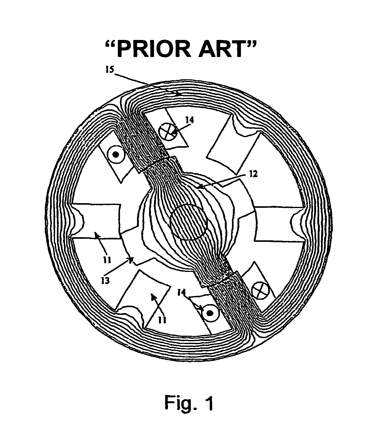
[0025]The electrical machines described in the prior-art have disadvantages that the present invention removes by using standard E-cores. The present invention is described in the following.

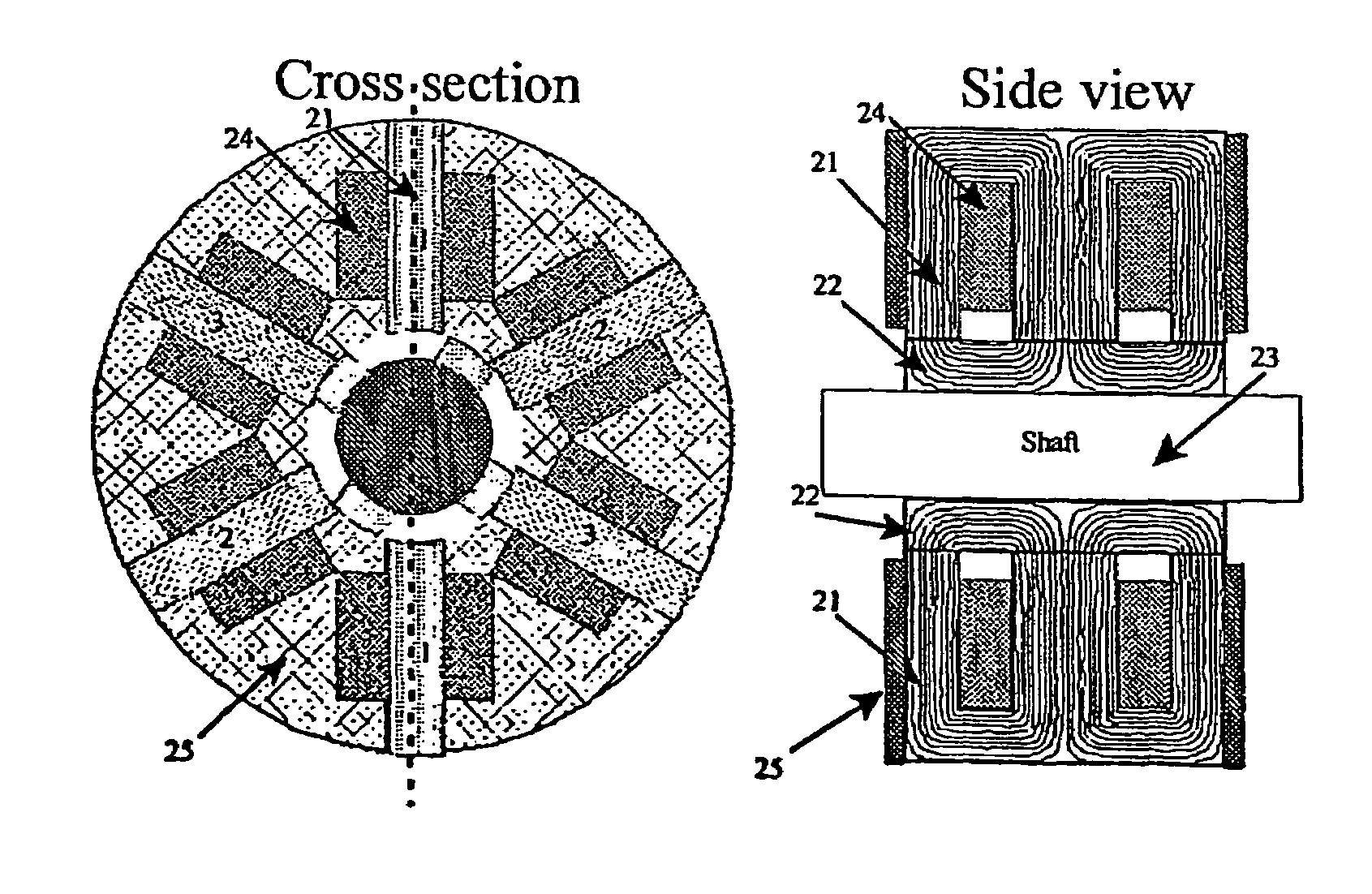
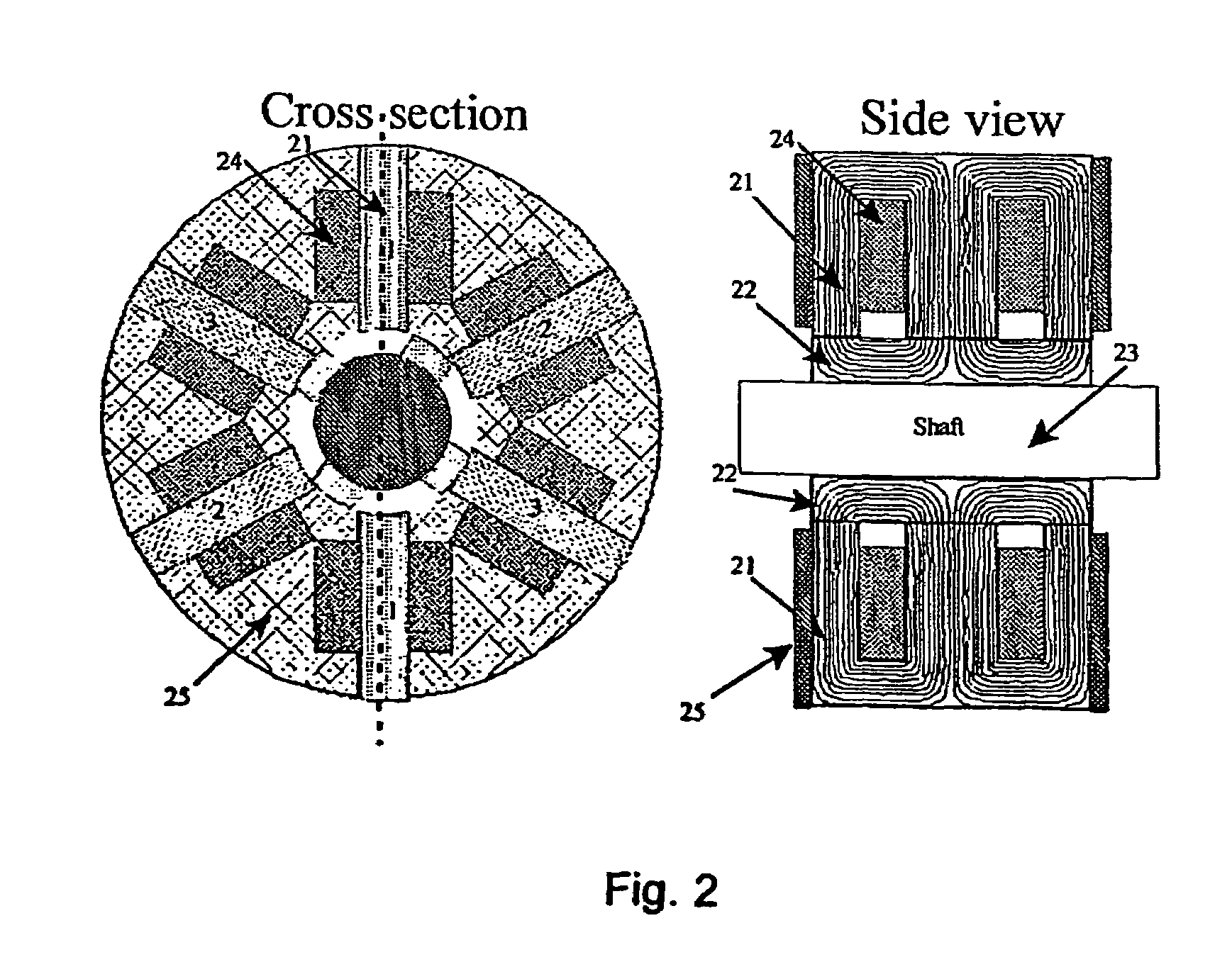
[0026]FIG. 2 illustrates an embodiment of an E-core transverse flux machine where the principle of using E-cores is adapted on the classical SRM. E-cores are traditionally used for single-phase transformers or as rectifier inductors and are characterised by having the shape of the letter ‘E’ and being constructed from oriented sheet steel which results in a higher flux densities and lower losses. E-cores are also made and sold in standard geometric forms, which can be a large advantage when producing small quantities of the E-core transverse flux machine.

[0027]By using E-cores 21 and its yoke / rotor section 22 the flux-path is short when compared to the classical SRM as the steel in the stator-yoke and rotor-yoke is non-existent. The yoke / rotor section is mounted on the shaft 23. The coils 24 will...


PUM


Abstract

In order to improve the torque per weight ratio in electrical machines for a lower price it is proposed to use a segmented stator design. The segmented stator design is based on general E shaped cores traditionally used for single-phased transformers and inductors, The E-cores has a coil around the centered leg and is assembled parallel to the rotor axis, which means it will function with the transverse flux principle. A radial flux principle can also be performed with the E-cores if the E-cores are divided into two U-sections with a full pitch winding in between them. A clear extra advantage with the E-cores is short flux paths meaning less steel has to be magnetised. For a low volume production standard E-cores can be used making the investment in production facilities smaller. The E-core machines using the transverse principle can have different pole-shapes such the normal force between the rotor and stator are significantly reduced. This makes unequal designs like a 3 stator- and 2 rotor-pole design practical possible.

Description

FIELD OF THE INVENTION[0001]The present invention relates to an electric rotating machine comprising a stator having a magnetic system comprising a plurality of individual core segments. In particular, the present invention relates to such a machine where the magnetic flux in the magnetic system is generated by windings arranged within outer legs of the core segments.BACKGROUND OF THE INVENTION[0002]An objective in the area of electrical machines in general is to make them more effective, such that they produce more torque with less weight and lower cost. Two electrical machine types have been in focus to full-fill this goal. These machines are the Permanent Magnet Transverse Flux Machine (PMTFM), and the switched reluctance machine (SRM). The PMTFM is well known for its high torque per weight ratio, but it is quite expensive and very difficult to manufacture because many parts are required. The SRM is one of the cheapest machines to manufacture and also has a reasonably good torque...

Claims


Application Information

Patent Timeline
Patent Type & Authority Patents(United States)
IPC IPC(8): H02K19/06H02K1/14H02K1/06H02K1/22H02K19/10
CPCH02K1/14H02K1/141H02K19/103H02K1/246H02K2201/12
Inventor RASMUSSEN, PETER OMAND
Owner ROCHE DIAGNOSTICS GMBH
Why Eureka
Try Eureka