Sliding bias controller for use with radio frequency power amplifiers

a bias controller and power amplifier technology, applied in amplifiers, amplifiers with semiconductor devices only, amplifiers with semiconductor devices, etc., can solve the problems of mainly attributed overall power consumption at lower power output levels, and not be suitable for all applications, so as to reduce current consumption, improve power amplifier efficiency, and reduce quiescent currents

Active Publication Date: 2008-01-01
QORVO US INC +1
View PDF7 Cites 50 Cited by
  • Summary
  • Abstract
  • Description
  • Claims
  • Application Information

AI Technical Summary

Benefits of technology

[0016]The present invention is a two stage power amplifier circuit that employs a sliding bias controller to reduce bias currents controlling the power amplifiers from their nominal levels at lower power output levels, thereby reducing the quiescent currents and improving power amplifier efficiency. Quiescent current is the current generated by the power amplifier when no input signal is present. At lower power output levels, reducing the quiescent currents allows the power amplifiers to operate using less current consumption to reduce DC power consumption and improve power amplifier efficiency. At higher power output levels, the sliding bias controller does not change the bias currents from their nominal levels so that bias currents are sufficient to operate the power amplifier at the necessary power output levels. This causes the power amplifiers to operate at or near higher efficiency Class B operation at lower output power levels, but at normal Class AB operation at higher output power levels.
[0017]A controllable supply voltage, such as a DC to DC converter, is also employed to control the supply voltage to the final stage power amplifier to further improve power amplifier efficiency.
[0018]A power level signal indicative of the power level of an input RF signal and generated by a power detector circuit is used to provide a voltage reference signal to both the DC to DC converter and the sliding bias controller. Thus, integration of the present invention with existing power amplifier circuits employing a power detector circuit that provides a control voltage to a controllable voltage supply is easily achieved. No extra reference generator is used for the sliding bias controller. Further, because the same power level signal is used as the reference signal to control the sliding bias controller and to control the controllable voltage supply, which generates the power amplifier supply voltage, extra calibration time that would be needed to calibrate two different reference signals for the sliding bias controller and the controllable voltage supply is eliminated.
[0019]Further, because the power detector is operating at high speeds, there are no bandwidth issues that affect the quiescent currents generated by the bias circuits when using the output of the power detector circuitry as the power level input into the sliding bias controller to ultimately control the bias currents generated by the bias circuits and thus the quiescent currents. The power detector may employ a high bandwidth low pass filter that is easily integrated into a monolithic microwave integrated circuit (MMIC).
[0020]The present invention can be implemented using any transistor technology such as Metal Oxide Semiconductor Field Effect Transistor (MOSFET) technology, Junction Field Effect Transistor (JFET) technology, or bipolar technology.

Problems solved by technology

However, diode based detectors still suffer from other issues such as delay or difficulty operating with small signal levels using phase modulation, and thus may not be suitable for all applications, as is well known.
Notably, the overall power consumption at lower power output levels is mainly attributed to the quiescent current and not amplification.

Method used


Image

  • Sliding bias controller for use with radio frequency power amplifiers
  • Sliding bias controller for use with radio frequency power amplifiers
  • Sliding bias controller for use with radio frequency power amplifiers

Examples


Embodiment Construction

[0032]The embodiments set forth below represent the necessary information to enable those skilled in the art to practice the invention and illustrate the best mode of practicing the invention. Upon reading the following description in light of the accompanying drawing figures, those skilled in the art will understand the concepts of the invention and will recognize applications of these concepts not particularly addressed herein. It should be understood that these concepts and applications fall within the scope of the disclosure and the accompanying claims.

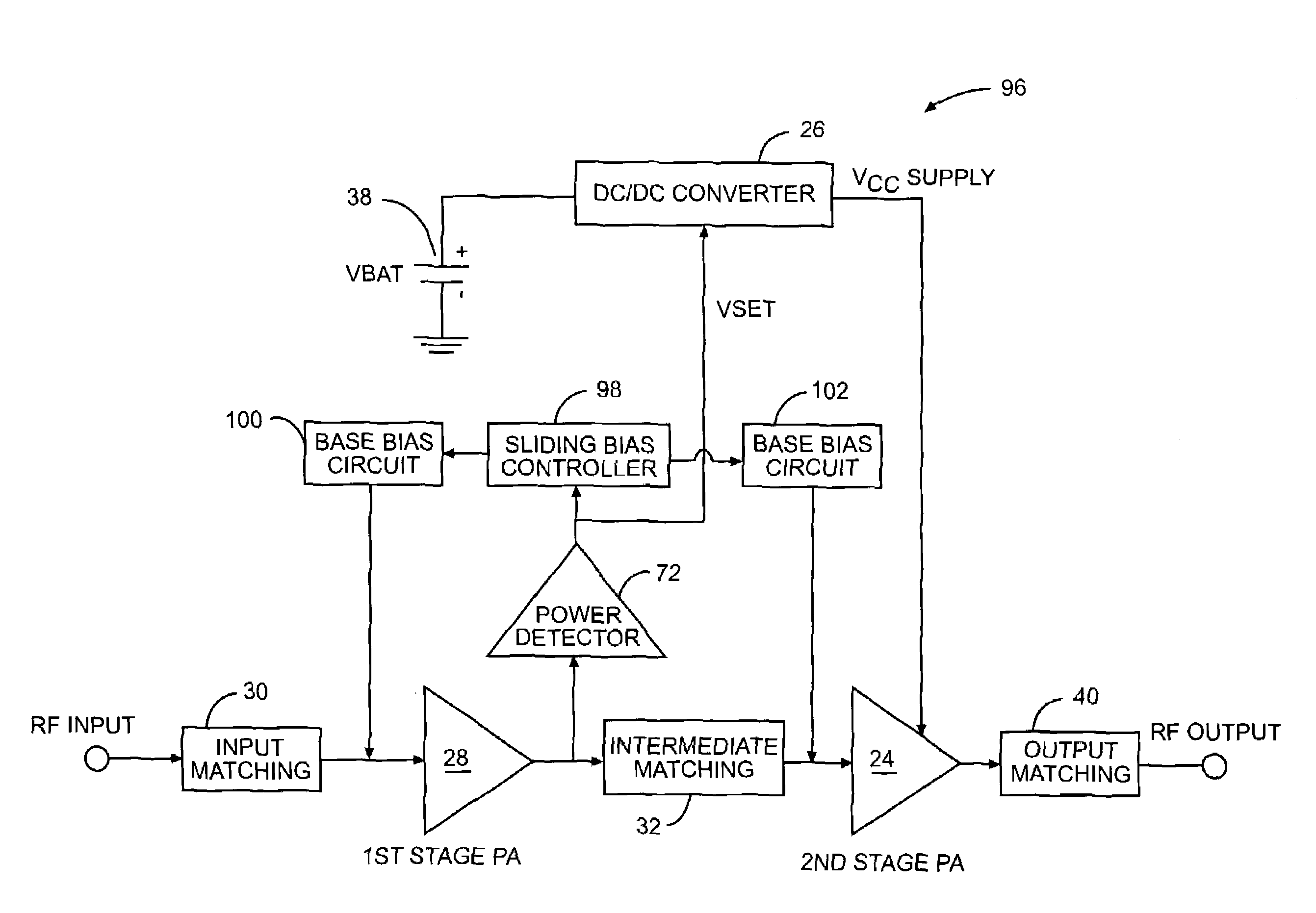
[0033]FIG. 6 illustrates a two stage power amplifier circuit 96 that employs a sliding bias controller 98 to control the bias currents of the power amplifier stages 24, 28 and thus the quiescent currents of the power amplifier stages 24, 28 as a result. The bias currents are generated by base bias circuit 100 and base bias circuit 102 to control the operation of the power amplifiers 24, 28. At lower power output levels, the slidin...


PUM


Abstract

A two stage power amplifier circuit that employs both a DC to DC converter and sliding bias controller to improve power amplifier efficiency. The control signal that is generated by the power detector circuit to control the input voltage to the DC to DC converter is also used to provide the reference voltage that controls the sliding bias controller. The sliding bias controller reduces the quiescent current of the power amplifiers by reducing the bias currents, and thus the DC voltage at lower power output levels driving the power amplifiers. This causes the power amplifiers to operate at or near higher efficiency Class B operation at lower power output levels. As the power level increases, the sliding bias controller reduces its control on the bias currents so that the power amplifier can be driven at necessary higher power output levels.

Description

RELATED APPLICATION[0001]The present application is related to U.S. patent application Ser. No. 11 / 273,739 entitled “RADIO FREQUENCY POWER DETECTION AND DECISION CIRCUIT USED WITH DC SUPPLY VOLTAGE CONTROLLED POWER AMPLIFIERS,” filed on Nov. 15, 2005, incorporated herein by reference in its entirety, and assigned to the same assignee as the present invention.FIELD OF THE INVENTION[0002]The present invention relates to a bias controller for controlling the bias current to radio frequency (RF) power amplifiers used in RF communication circuitry to improve amplifier operating efficiency.BACKGROUND OF THE INVENTION[0003]RF power amplifiers are commonly used in RF circuits as the last active stage in RF transmitters. As a result, an RF power amplifier is typically the largest power consumption device in an RF system; therefore, RF power amplifier systems are designed to be as efficient as possible.[0004]One commonly used technique for improving the efficiency of an RF power amplifier is ...

Claims


Application Information

Patent Timeline
Patent Type & Authority Patents(United States)
IPC IPC(8): H03G3/10
CPCH03F1/0227H03F1/0261H03F2200/15H03F2200/411H03F2200/451
Inventor LEE, JONGSOOSPEARS, EDWARD T.
Owner QORVO US INC
Why Eureka
Try Eureka