

Flow reactors for chemical conversions with heterogeneous catalysts
a flow reactor and catalyst technology, applied in the direction of physical/chemical process catalysts, indirect heat exchangers, lighting and heating apparatus, etc., can solve the problems of reducing the conversion rate, throughput and/or yield of value added products, and the catalyst is likely to overheat, and the heat generated during the reaction is difficult to balance the heat removal capability of the heat transfer medium with the heat generated during the reaction
- Summary
- Abstract
- Description
- Claims
- Application Information
AI Technical Summary
Benefits of technology
Problems solved by technology
Method used
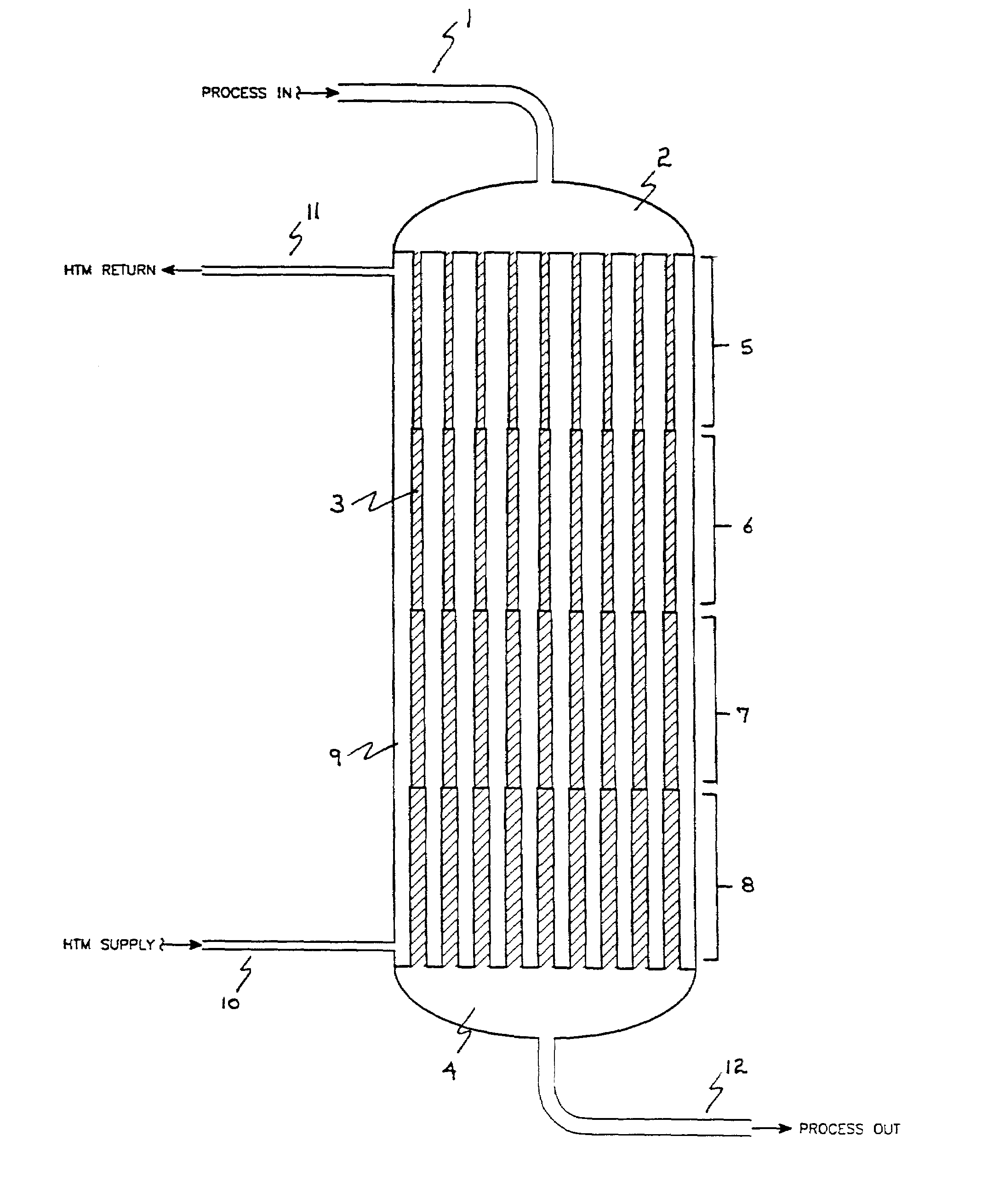
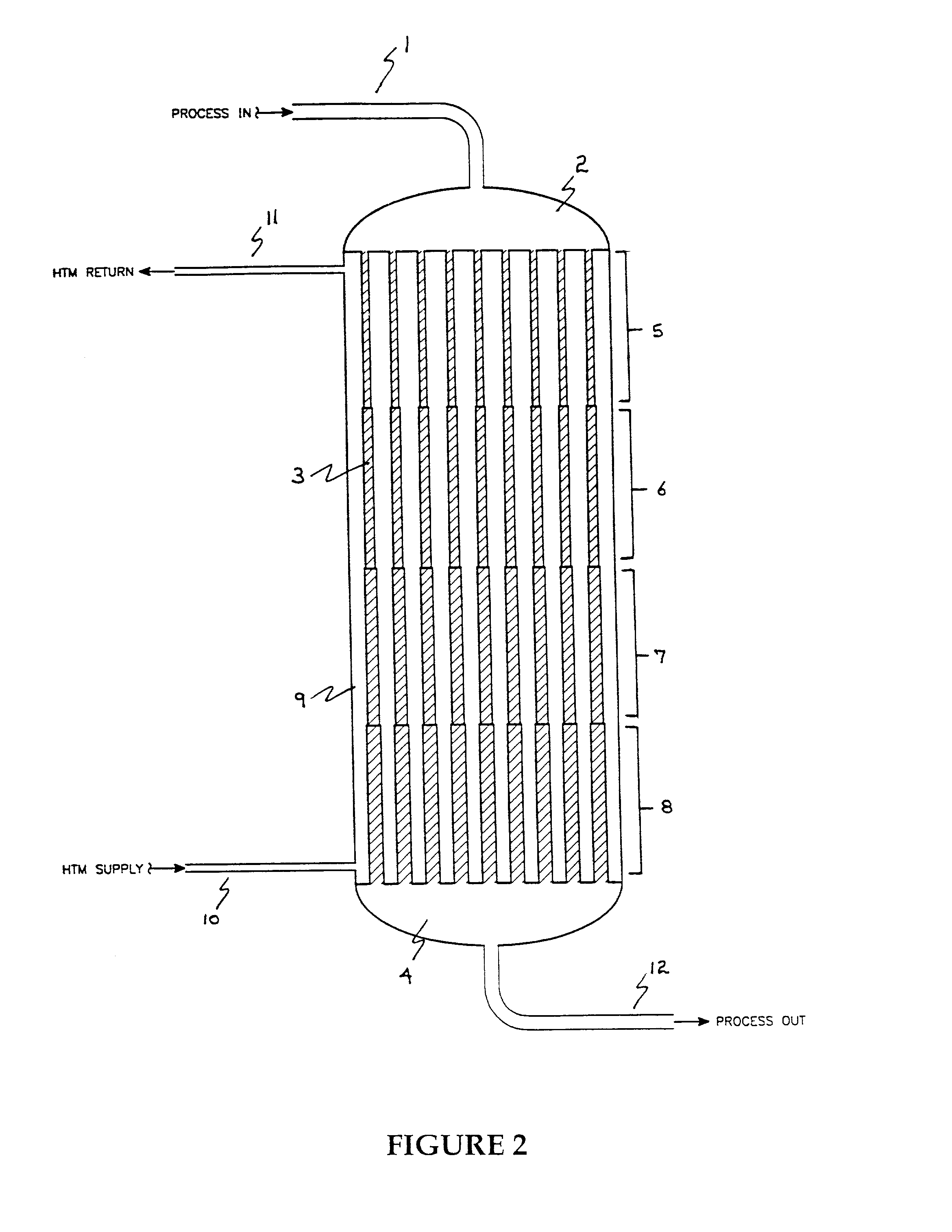
Image


Examples
example 1
[0099]In this example the test program described above was used to demonstrate a reactor having a volume for catalyst of about 613 cm3 distributed according to the invention into four contiguous cylindrical zones as shown in Table 1.
[0100]
TABLE 1Percent ofCatalystTubeTubeFraction ofTotal CatalystGeometricZoneLengthI.D.Axial LengthVolumeFactor × 102I14 in.0.81 in.0.291719.287.37II12 in.0.87 in.0.250019.079.23III12 in.0.98 in.0.250024.2910.42IV10 in.1.33 in.0.208337.3616.99
Concentration of butane in the feed was 1.5 mole percent. At 2000 VHSV in the catalyst zone and a molten salt temperature of 395° C., the maleic anhydride yield was 91 percent by weight after the catalyst was fully activated. The temperature profile of the catalyst bed exhibited a maximum of 446° C.
example 2
[0101]In this example the test program described above was used to demonstrate a reactor having a volume for catalyst of about 620 cm3 distributed according to the invention into four contiguous cylindrical zones as shown in Table II.
[0102]
TABLE IIPercent ofCatalystTubeTubeFraction ofTotal CatalystGeometricZoneLengthI.D.Axial LengthVolumeFactor × 102I14 in.0.81 in.0.291719.287.37II14 in.0.87 in.0.291722.017.91III14 in.1.12 in.0.291736.7410.22IV 6 in.1.33 in.0.125022.1828.31
Concentration of butane in the feed was 1.5 mole percent. At 2000 VHSV in the catalyst zone and a molten salt temperature of 389° C., the maleic anhydride yield was 90 percent by weight after the catalyst was fully activated. The temperature profile of the catalyst bed exhibited a maximum of 426° C.
example 3
[0103]In this example the test program described above was used to demonstrate a reactor having a volume for catalyst of about 616 cm3 distributed according to the invention into four contiguous cylindrical zones as shown in Table III.
[0104]
TABLE IIIPercent ofCatalystTubeTubeFraction ofTotal CatalystGeometricZoneLengthI.D.Axial LengthVolumeFactor × 102I12 in.0.74 in 0.250014.647.91II12 in.0.87 in.0.250018.989.23III13 in.1.12 in.0.270826.199.62IV11 in.1.33 in.0.229240.1915.44
Concentration of butane in the feed was 1.5 mole percent. At 2000 VHSV in the catalyst zone and a molten salt temperature of 384° C., The maleic anhydride yield was 89 percent by weight after the catalyst was fully activated. The temperature profile of the catalyst bed exhibited a maximum of 455° C.
PUM
| Property | Measurement | Unit |
|---|---|---|
| total length | aaaaa | aaaaa |
| total length | aaaaa | aaaaa |
| temperatures | aaaaa | aaaaa |
Abstract
Description
Claims
Application Information