Electric double layer capacitor

a double-layer capacitor and capacitor technology, applied in the direction of capacitor details, electrolytic capacitors, hybrid cases/housings/encapsulations, etc., can solve the problems of unfavorable leakage of electrolytic solution, etc., to achieve large thermal expansion coefficient, excellent heat resistance, and difference in thermal coefficien

Active Publication Date: 2008-01-08
FDK CORP
View PDF7 Cites 2 Cited by
  • Summary
  • Abstract
  • Description
  • Claims
  • Application Information

AI Technical Summary

Benefits of technology

[0011]By the use of polyether ether ketone which is excellent in heat resistance and has a relatively larger coefficient of thermal expansion than that of a conventional product as a gasket, the difference in coefficient of thermal expansion from a metal such as a stainless steel which is the material for the exterior cover and the exterior case is reduced. Whereas, polyether ether ketone is lower in thermal deformation temperature than other resin materials, and high in heat-resistant use temperature. Therefore, upon the expansion of the exterior cover and the exterior case, it keeps the hermeticity in response to the deformed shape. Whereas, no folded-back part is provided at the outer circumferential part of the exterior cover. This can reduce the range of thermal expansion in the reflow step as compared with conventional products. By these synergistic effects, it is possible to prevent the formation of the gap between the exterior cover and the gasket, or the gasket and the exterior case even in a reflow step at about 260° C. As a result, it is possible to provide an electric double layer capacitor which is less likely to undergo the leakage of the electrolytic solution.

Problems solved by technology

The electrolytic solution unfavorably leaks therefrom.
This problem remarkably appears with an increase in temperature of the reflow furnace, which causes the leakage of the electrolytic solution.
This unfavorably tends to cause leakage,

Method used


Image

  • Electric double layer capacitor
  • Electric double layer capacitor
  • Electric double layer capacitor

Examples


example 1

[0029]An electric double layer capacitor in the invention was manufactured according to the following procedure.

[0030](Manufacturing of Polarizing Electrode)

[0031]An activated carbon, acetylene black, and polytetrafluoroethylene were mixed so as to achieve a weight ratio of 90:5:5. The mixture was formed into a disk with a diameter of 2 mm and a thickness of 0.5 mm, and then, vacuum dried at 150° C. for 2 hours thereby manufacturing a first polarizing electrode and a second polarizing electrode.

[0032](Manufacturing of Electrolytic Solution)

[0033]In an organic solvent in which propylene carbonate and sulfolane were mixed in a volume ratio of 50:50, triethylmethylammonium tetrafluoroborate which was a supporting salt was dissolved so as to achieve a concentration of 1:0 mol / l; thereby manufacturing an electrolytic solution.

[0034](Fabrication of Coin Type Cell)

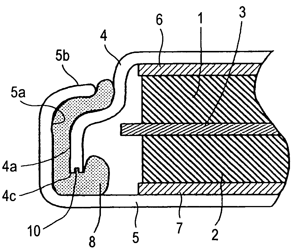
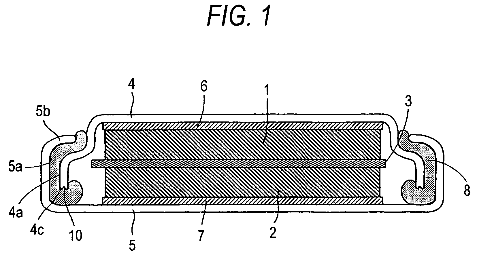
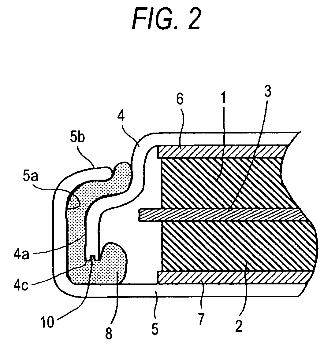
[0035]As shown in FIG. 2, on the bottom surfaces of an exterior cover (4) not provided with a folded-back part at the outer cir...


PUM


Abstract

An electric double layer capacitor including a separator, a pair of polarizing electrodes disposed opposite to each other with the separator interposed therebetween, an electrolytic solution impregnated in a pair of the polarizing electrodes and the separator, an exterior cover and an exterior case for accommodating the separator, a pair of the polarizing electrodes, and the electrolytic solution, and a gasket disposed between the outer circumferential part of the exterior cover and the inner circumferential part of the exterior case, the storage space formed by the exterior case and the exterior cover being hermetically sealed by inwardly bending the opening tip portion of the exterior case, is characterized in that no folded-back part is provided at the outer circumferential part of the exterior cover, and the gasket is polyether ether ketone.

Description

TECHNICAL FIELD[0001]The present invention relates to an electric double layer capacitor which includes a pair of polarizing electrodes opposite to each other with a separator interposed therebetween, impregnated with an electrolytic solution.BACKGROUND ART[0002]For an electric double layer capacitor having a coin type structure, the structure as shown in FIG. 6 is generally known. Namely, a first polarizing electrode (1) including an activated carbon or the like and a second polarizing electrode (2) including an activated carbon or the like are disposed opposite to each other with a separator (3) interposed therebetween. Thus, the first polarizing electrode (1) and the second polarizing electrode (2) are provided with a first current collector (6) and a second current collector (7), respectively. A pair of the polarizing electrodes (1) and (2), and the separator (3) are impregnated with an electrolytic solution. The components are accommodated in the storage space formed by an exte...

Claims


Application Information

Patent Timeline
Patent Type & Authority Patents(United States)
IPC IPC(8): H01G9/00H01G9/10H01G11/22H01G11/24H01G11/38H01G11/42H01G11/78H01G11/80H01G11/84
CPCH01G9/10H01G9/155Y02E60/13H01G11/80H01G11/78
Inventor OMURA, SEIJINAKAJIMAKAWATA, YOHEISHIRASAKA, MITSURU
Owner FDK CORP
Why Eureka
Try Eureka