
Optical packet switching system

a packet switching and optical technology, applied in data switching networks, multiplex communication, digital transmission, etc., can solve the problems of difficult to obtain the desired optical signal to noise ratio (osnr), large loss even in a transparent state, and inability to limit processing speed, so as to improve the osnr, improve the system management, and efficiently locate the fault

Inactive Publication Date: 2008-01-08
FUJITSU LTD
View PDF6 Cites 29 Cited by
  • Summary
  • Abstract
  • Description
  • Claims
  • Application Information

AI Technical Summary

Benefits of technology

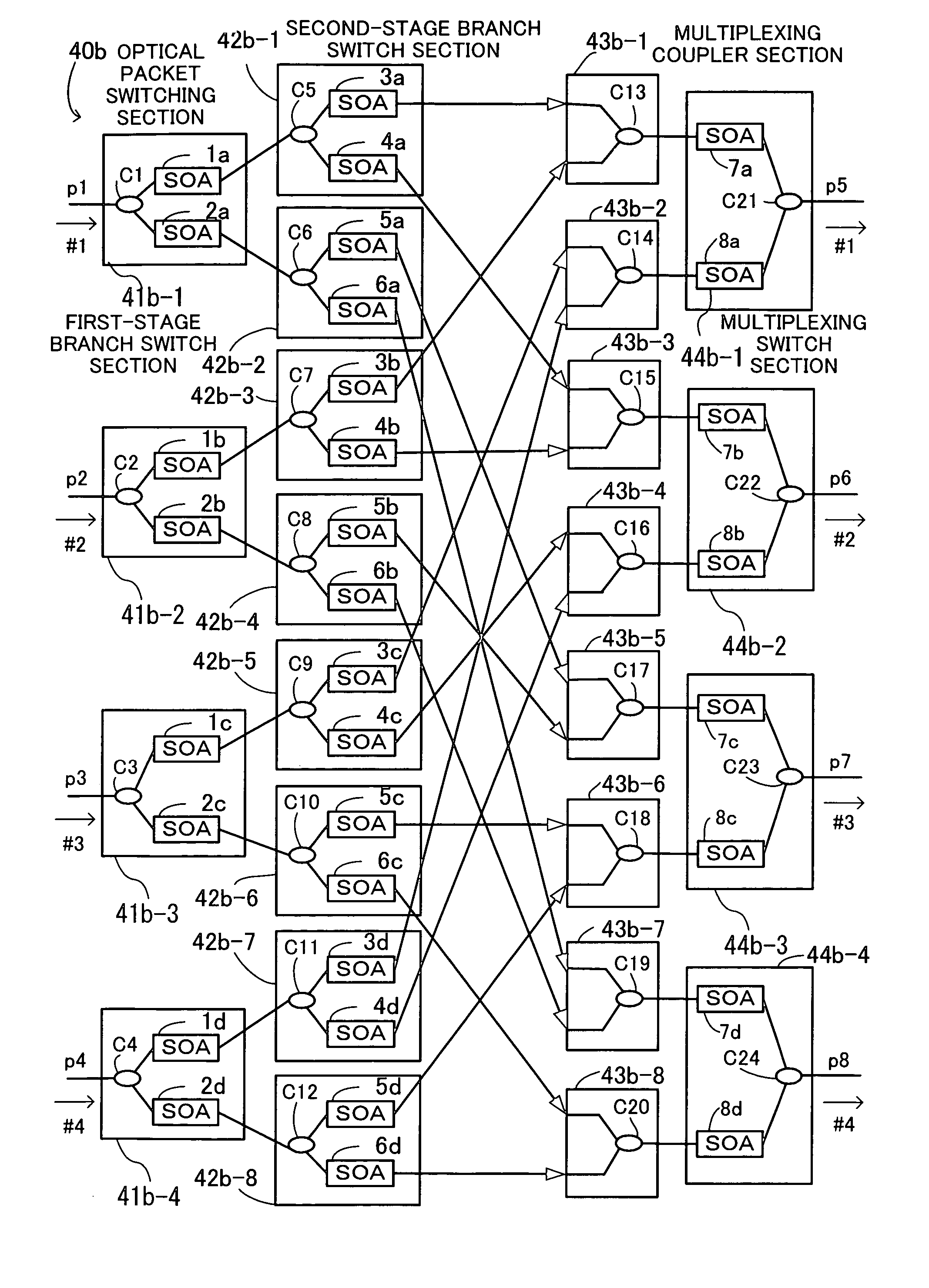
[0045]The present invention was made under the background circumstances described above. An object of the present invention is to provide an optical packet switching system in which transmission quality, reliability, and system management in optical packet switching control are improved by reducing a crosstalk component from adjacent ports, improving an OSNR, and efficiently locating a fault.

Problems solved by technology

Compared with the conventional switching in which optical signals are temporarily converted into electrical signals, processing speeds are not limited by electronic processing but by light propagation delay time.
Electro-absorption gate switches have the defect of, for example, a large loss even in a transparent state.
If a large-capacity switching system with many ports is built in this way by using the conventional structure, the following problems arise.
It is difficult to obtain a desired optical signal to noise ratio (OSNR).
In addition, it is difficult to locate a fault in a switching system using SOAs.
As a result, it is difficult to identify the signal component selected by the SOA at the output stage of the multiplexing coupler.
Therefore, a bit error rate drops significantly.
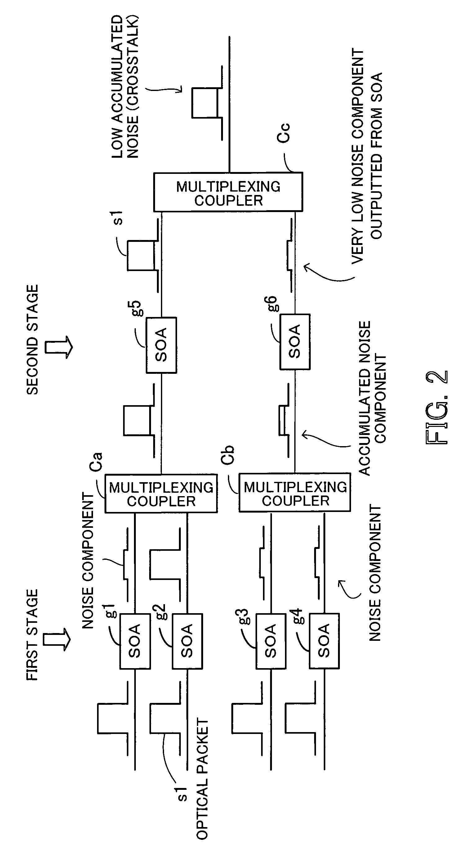
As stated above, the level of a crosstalk component from adjacent ports which is negligible in a switching system including a small number of ports is too high in a large-scale switching system including a large number of ports to neglect.
In addition, the level of accumulated noise due to SOAs is low.
In a large-scale switching system including a large number of ports, however, the number of branches by branch couplers is large and great branch loss occurs.
In addition, the level of accumulated noise due to SOAs is high.
If optical output is sent from an input line card at the input port #1 and the optical packet is not received at the output port #1, there is a strong possibility that a fault has occurred in the SOA 52a-1.
In such a system in which the multistage connection of SOAs is made, it is impossible to locate a fault by the above simple method.
Even if an optical packet is not received at an output port, it is impossible to locate one of the n SOAs in which a fault has occurred.
However, this method cannot be applied.
However, such a state supervision mechanism cannot be applied in the same way to optical packet switching systems including multistage-connected SOAs.
Therefore, the ordinary state supervision mechanism using a PD cannot be applied to an SOA.
If some fault occurs in an SOA in such a switching system, there has conventionally been no effective fault locating mechanism.
This makes it very difficult to locate the SOA in which the fault has occurred, resulting in degradation in reliability.
In conventional switching systems using SOAs, however, as their scale increases, the above problems become more marked and transmission quality is degraded.

Method used


Image

  • Optical packet switching system
  • Optical packet switching system
  • Optical packet switching system

Examples


Embodiment Construction

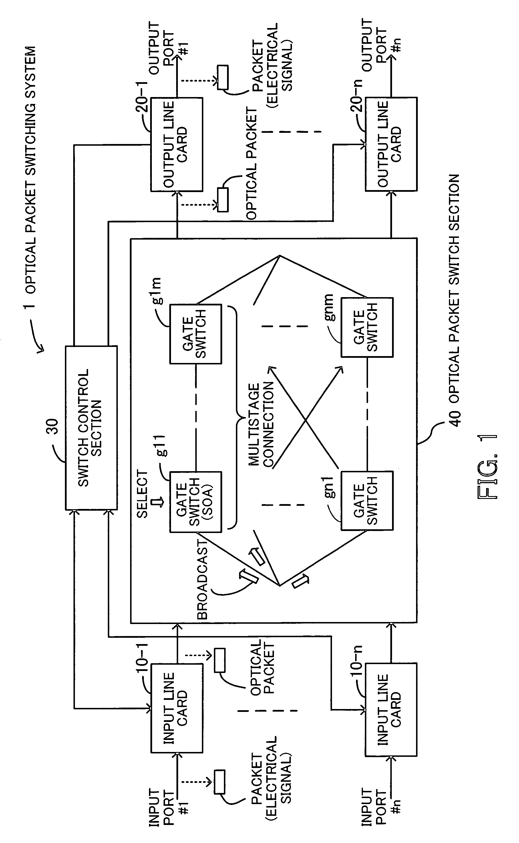
[0077]Embodiments of the present invention will now be described with reference to the drawings. FIG. 1 is a view for describing the principles underlying an optical packet switching system. An optical packet switching system 1 comprises input line cards 10-1 through 10-n, output line cards 20-1 through 20-n, a switch control section 30, and an optical packet switch section 40 and performs broadcast-select optical packet switching with an integrated gate switch.

[0078]When the input line cards 10-1 through 10-n receive packets (electrical signals) from input ports #1 through #n respectively, the input line cards 10-1 through 10-n generate port connection requests for connecting the input ports #1 through #n and output ports #1 through #n and send the port connection requests to the switch control section 30. In addition, the input line cards 10-1 through 10-n convert the packets into optical packets (E / O conversion) and send them to the optical packet switch section 40. Hereinafter t...


PUM


Abstract

An optical packet switching system in which transmission quality, reliability, and system management in optical packet switching control are improved. An optical packet switch section includes semiconductor optical amplifiers as gate switches multistage-connected on paths along which optical packets sent from a plurality of input line cards are transmitted and performs optical packet switching by broadcasting the optical packets to a plurality of gate switches, by selecting the optical packets by ON / OFF gating operation of the gate switches, and by absorbing noise signals which flow along non-selected paths by putting gate switches at a final stage into the OFF state. A switch control section exercises ON / OFF drive control over the gate switches in the optical packet switch section on the basis of port connection requests from the plurality of input line cards so as to generate requested paths.

Description

CROSS-REFERENCE TO RELATED APPLICATIONS[0001]This application is based upon and claims the benefits of priority from the prior Japanese Patent Application No. 2005-093469, filed on Mar. 29, 2005, the entire contents of which are incorporated herein by reference.BACKGROUND OF THE INVENTION[0002](1) Field of the Invention[0003]This invention relates to an optical packet switching system and, more particularly, to an optical packet switching system for performing optical packet transmission.[0004](2) Description of the Related Art[0005]With an increase in demand for communication by broadband services, in recent years long-distance large-capacity optical communication networks have appeared and development of high-speed large-capacity wavelength division multiplexing (WDM), in which a plurality of optical signals with different wavelengths are multiplexed into a single optical fiber, have advanced.[0006]In addition, with the rapid spread of the Internet and an increase in the number of...

Claims


Application Information

Patent Timeline
Patent Type & Authority Patents(United States)
IPC IPC(8): H04J14/00H04B10/07H04B10/2507H04L12/931H04B10/27H04B10/293
CPCH04Q11/0005H04Q11/0066H04Q2011/0013H04Q2011/0015
Inventor AOKI, YASUHIKO
Owner FUJITSU LTD
Learn More