Magnetically attracted inspecting apparatus and method using a fluid bearing

a fluid bearing and magnetic attraction technology, applied in the direction of magnetic property measurement, instruments, specific gravity measurement, etc., can solve the problems of semi-automated inspection system, time-consuming manual scanning of structures, prone to human error, and inability to disassemble, etc., to achieve continuous inspection, increase access to surfaces, and maintain the alignment and positioning of sensing transducers.

Inactive Publication Date: 2008-01-22
THE BOEING CO
View PDF27 Cites 17 Cited by
  • Summary
  • Abstract
  • Description
  • Claims
  • Application Information

AI Technical Summary

Benefits of technology

[0013]An improved apparatus and method for inspecting a structure, such as a composite structure and, especially a curved composite structure, provides fluid bearing support for magnetically coulped inspection probes. An inspection apparatus or method according to an embodiment of the present invention may advantageously provide increased access to surfaces of a structure for inspection and allow for continuous inspection of large areas of a structure while maintaining alignment and positioning of sensing transducers and / or receivers. The method and apparatus of the present invention use probes including respective sensing elements, such as ultrasonic transducers, that are disposed proximate the opposed surfaces of a structure. Only one of the probes need be driven. Thus, the method and apparatus of the present invention are advantageously adapted to inspect structures in which one surface of the structure is relatively inaccessible. Additionally, embodiments of the method and apparatus of the present invention are capable of operating in an ultrasonic array mode, even in conjunction with the inspection of curved structures, thereby increasing the speed and efficiency with which such structures may be inspected and correspondingly reducing the cost associated with the inspection. Further, embodiments of the method and apparatus of the present invention permit the probes to be suspended against and glide along the respective surfaces of the structure. Thus, embodiments of the present invention may reduce the necessary sophistication of the motion control system that is otherwise required by conventional scanning systems to maintain the ultrasonic probes in a predefined orientation and at a predefined spacing from the respective surface of a structure undergoing inspection and may maintain alignment between the probes or the sensors of the probes.
[0014]The apparatus of the present invention includes a driven probe disposed proximate a first surface of the structure and a tracking probe disposed proximate an opposed second surface of the structure. The driven probe is moved along the first surface of the structure in response to the application of motive force, such as by means of a robotic arm or other positioning system. In contrast, the tracking probe generally moves along the second surface of the structure in response to the movement of the driven probe and independent of the application of any other motive force. Thus, the tracking probe generally passively follows the movement of the driven probe such that the tracking probe need not be engaged by a robotic arm or other positioning system. The tracking probe can therefore be disposed on the backside or other surface of a structure that is relatively inaccessible.
[0017]To facilitate the coupling of the ultrasonic signal between the ultrasonic transducer of the driven probe and the structure, a couplant may be disposed between the ultrasonic transducer and the respective surfaces of the structure. While air or water jets may be used as a couplant, the driven probe of one advantageous embodiment may instead include an inlet for fluid that is pumped between the ultrasonic transducer and the first surface of the structure. In this regard, the driven probe may include a housing in which the magnet and the ultrasonic transducer are disposed, and which defines the inlet. The housing may also define a fluid conduit to direct fluid flow from the inlet to a plurality of channels to disperse the flow of fluid between the probe and the second surface of the structure. The plurality of channels may be, for example, a series of radially directed recesses or a plurality of holes. The fluid conduit may be in fluid communication with that portion of the ultrasonic transducer that faces the first surface of the structure. Thus, the fluid that is pumped between the ultrasonic transducer and the first surface of the structure may facilitate coupling of the ultrasonic signals produced by the ultrasonic transducer into the structure. Likewise, the tracking probe may include an inlet for fluid that is pumped between the ultrasonic transducer of the tracking probe and the second surface of the structure. In this regard, the tracking probe can also include a housing in which the magnet and the ultrasonic transducer are disposed, and which defines the inlet. The housing may also define a fluid conduit to direct fluid flow from the inlet to a plurality of channels to disperse the flow of fluid between the probe and the first surface of the structure. The plurality of channels may be, for example, a series of radially directed recesses or a plurality of holes. Again, the fluid conduit may be in fluid communication with that portion of the ultrasonic transducer of the tracking probe that faces the second surface of the structure. Thus, ultrasonic signals emerging from the structure may be effectively coupled to the ultrasonic transducer of the tracking probe by the fluid that is pumped therebetween. By pumping fluid between the ultrasonic transducers and the respective surfaces of the structure, water jets are not required such that the ultrasonic transducers of the driven and tracking probes may include arrays of ultrasonic transducers, thereby permitting the rate at which the structure is inspected to be increased and the associated inspection cost accordingly decreased.
[0019]According to another aspect of the present invention, a method of inspecting a structure is provided. In this regard, the driven probe is positioned proximate the first surface of the structure, and the tracking probe is positioned proximate the opposed second surface of the structure. For example, driven and tracking probes may be suspended by bearing contact above the first and second surfaces of the structure, respectively, thereby simplifying the alignment and spacing of the probes relative to the respective surfaces of the structure and relative to the other probe or a sensor of the other probe. The method of inspecting a structure also establishes magnetic attraction between the driven and tracking probes such that the driven and tracking probes are drawn toward the first and second surfaces of the structure, respectively. The driven probe is then moved along the first surface of the structure, such as in response to the application of a motive force by a robotic arm or other positioning system. The movement of the driven probe and the magnetic attraction between the driven and tracking probes causes the tracking probe to be correspondingly moved along the second surface of the structure. Advantageously, the tracking probe moves along the second surface of the structure independent of the application of any motive force. Thus, the tracking probe may be disposed proximate a relatively inaccessible surface of a structure since the movement of the tracking probe need not be controlled by a robotic arm or other positioning system.
[0020]As the driven probe is moved along the first surface of the structure, ultrasonic signals are transmitted to the structure by the ultrasonic transducer of one of the probes and are received by the ultrasonic transducer of the other probe following propagation through the structure. The driven and / or tracking probes are advantageously spaced from the respective surface by bearing contact. For example, a fluid may be pumped between the driven and / or tracking probes and the first and second surfaces of the structure, respectively, to create a bearing contact between the probes and the structure to suspend the probes above the respective surfaces and to permit smooth translation of the probes along the surfaces of the structure. To effectively couple the ultrasonic signals between the driven and tracking probes and the structure, a fluid may be pumped between the sensors of the driven and tracking probes and the first and second surfaces of the structure, respectively, while ultrasonic signals are transmitted into and received from the structure. In embodiments in which fluid is used to create bearing contact, the fluid may also serve as the couplant. Additionally, or alternatively, air or water jets may be used as the couplant.

Problems solved by technology

However, access to interior surfaces is often more difficult or impossible without disassembly, such as removing a part for inspection from an aircraft.
For example, typical flaws in composite sandwich structures, generally made of one or more layers of lightweight honeycomb or foam core material with composite or metal skins bonded to each side of the core, include disbonds which occur at the interfaces between the core and the skin or between the core and a septum intermediate skin.
Thus, manual scanning of structures is time-consuming, labor-intensive, and prone to human error.
However, for through-transmission ultrasonic inspection, a semi-automated inspection system requires access to both sides or surfaces of a structure which, at least in some circumstances, will be problematic, if not impossible, particularly for semi-automated systems that use a fixed frame for control of automated scan heads.
Conventional automated scanning systems, such as the AUSS-X system, therefore require access to both sides or surfaces of a structure which, at least in some circumstances, will be problematic, if not impossible, particularly for very large or small structures.
This requirement that the orientation and spacing of the ultrasonic transmitter and receiver be invariant with respect to one another and with respect to the structure undergoing inspection is especially difficult in conjunction with the inspection of curved structures.
Furthermore, manual, semi-automated, and automated scanning systems typically are limited in the size of a structure that can be inspected, generally limited to areas just a few meters square and typically limited to much smaller areas, although some larger, more complicated systems are available.
Stiffness and weight limitations often restrict the distance a manual, semi-automated, or automated system may be able to extend inspection devices over a structure for inspection.
Thus, large composite structures may not be capable of complete inspection.
For example, contemporary inspection methods are not well suited for inspecting a Sea Launch payload fairing with a diameter of approximately four meters, a cylindrical length of approximately five meters, and an overall length of over twelve meters.
Unfortunately, the use of arrays of ultrasonic transmitters and receivers is generally impractical during the scanning of curved structures, such as large-scale curved composite structures.
While some array systems may be capable of scanning gently sloping structures, more complicated curved structures typically are impractical to inspect with an array, such as requiring that the array system be flexible.
In instances in which the ultrasonic probes include an array of ultrasonic transmitters or receivers, it has been difficult to design a corresponding water jet array that does not produce significant interference or crosstalk between the elements of the array.
Access to the structure requiring inspection may be so limited that a manual inspection by a technician or a semi-automated or automated system is not possible, typically due to systems requiring access to exterior and interior surfaces of the structure to be inspected.
For example, the backside of an inlet duct for an Unmanned Combat Air Vehicle (UCAV) or an F-35 has limited access for inspection.
Alignment and positioning of sensors such as transducers is similarly complicated by accessibility to the structure such as inaccessibility to one side of a composite structure.

Method used


Image

  • Magnetically attracted inspecting apparatus and method using a fluid bearing
  • Magnetically attracted inspecting apparatus and method using a fluid bearing
  • Magnetically attracted inspecting apparatus and method using a fluid bearing

Examples


Embodiment Construction

[0038]The present invention will be described more fully with reference to the accompanying drawings. Some, but not all, embodiments of the invention are shown. The invention may be embodied in many different forms and should not be construed as limited to the embodiments described. Like numbers and variables refer to like elements and parameters throughout the drawings.

[0039]I. Fluid Bearing Magnetically Coupled Inspection Probes

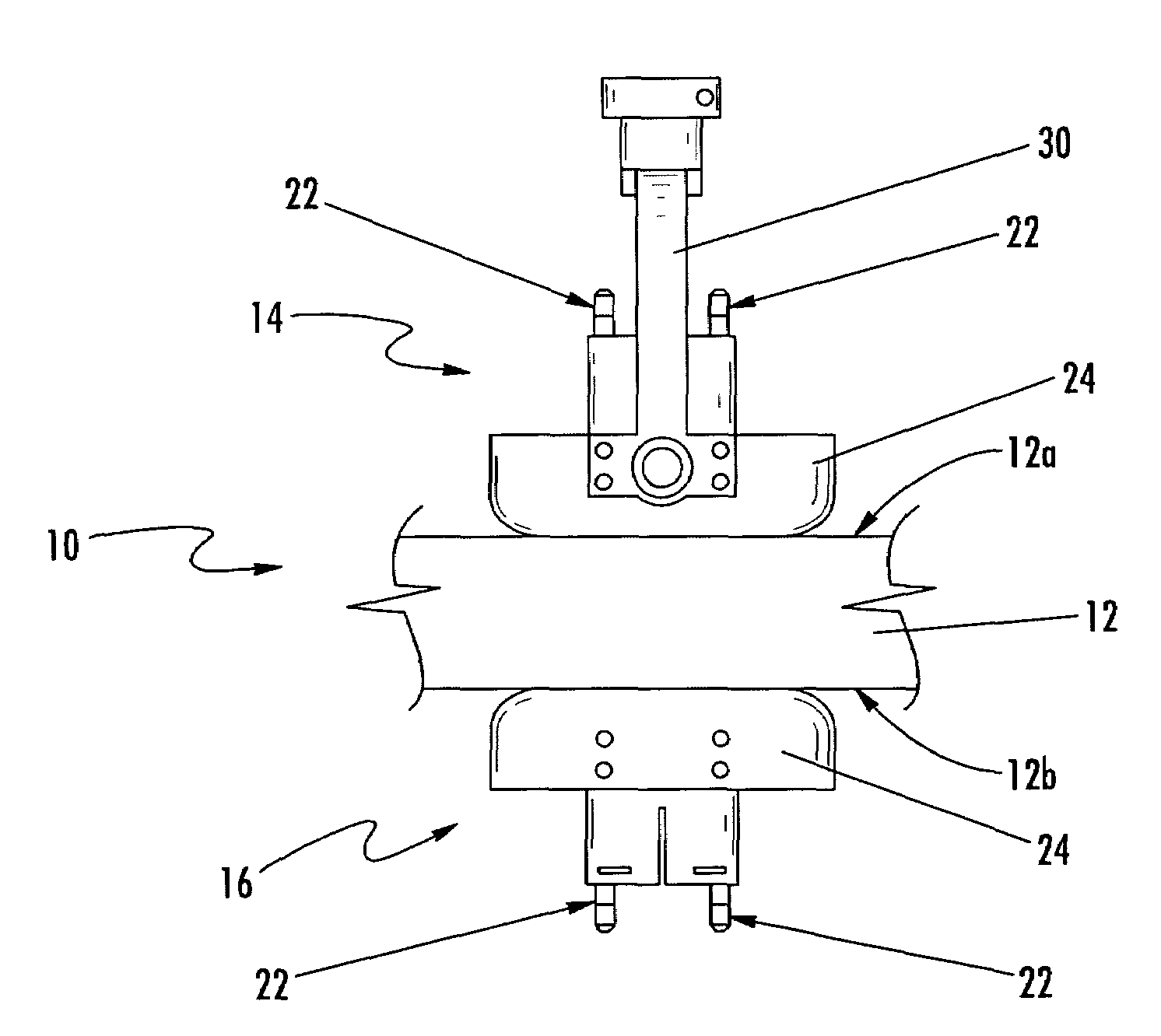
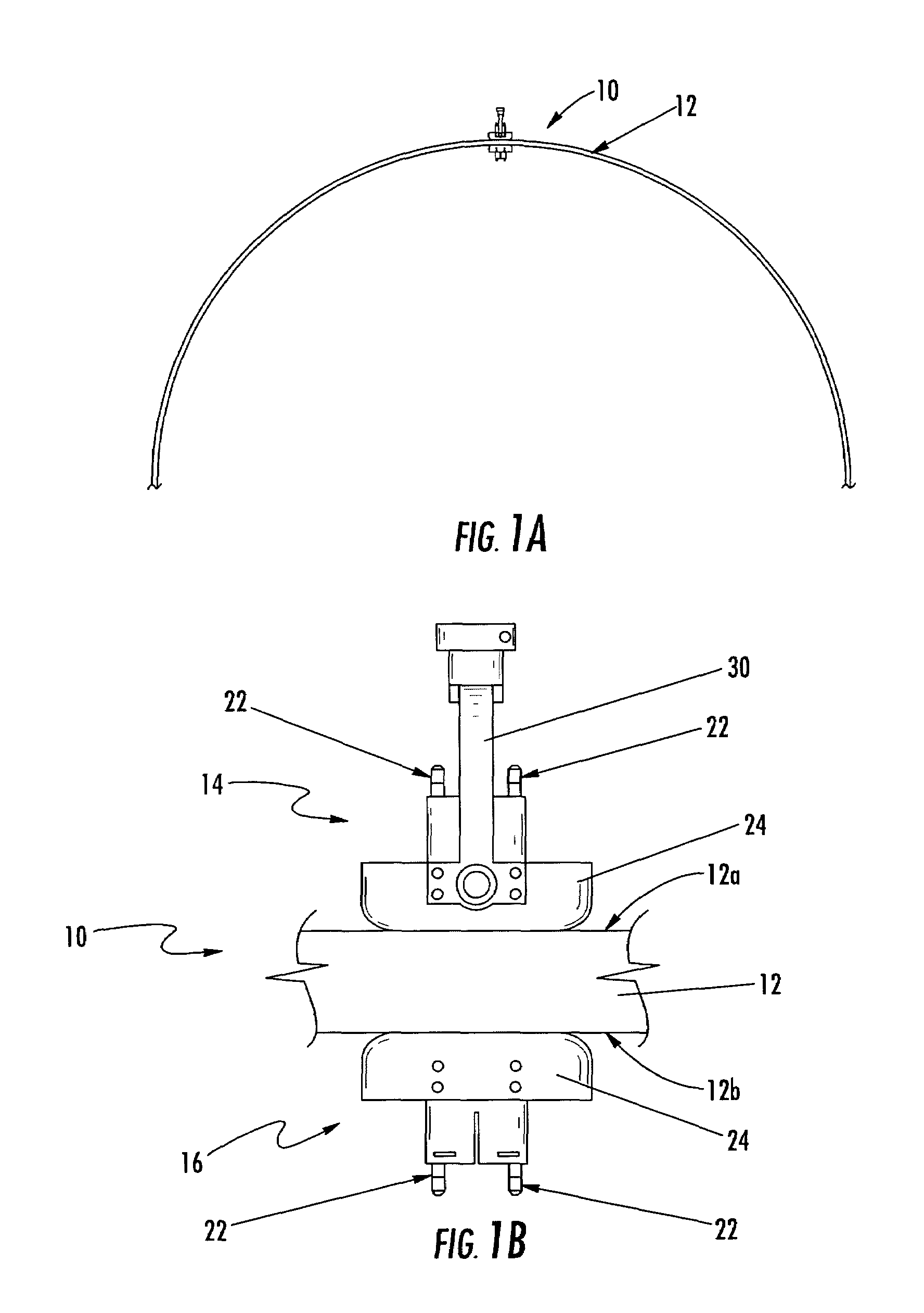
[0040]Referring now to FIGS. 1A and 1B, an apparatus 10 for inspecting a structure 12 according to one embodiment of the present invention is depicted. The apparatus can inspect a variety of structures formed of various materials. Since the apparatus relies to some extent upon the establishment of magnetic fields through the structure, however, the structure is preferably non-magnetic, that is, the structure preferably has no magnetic permeability. Structures that may be inspected with an embodiment of an inspection device of the present invention may inclu...


PUM

PropertyMeasurementUnit
lengthaaaaaaaaaa
lengthaaaaaaaaaa
diameteraaaaaaaaaa

Abstract

An apparatus and method for inspecting a structure are provided which include probes with sensing elements and are disposed proximate opposite surfaces of a structure, where only one of the probes need be driven. A tracking probe may be magnetically coupled to a driven probe and move in coordination therewith. Ring magnets may be used in the driven and tracking probes to provide the magnetic coupling and align sensing elements disposed in the centers of the ring magnets. The probes may include a fluid bearing, such as a water bearing or an air bearing, for supporting the structure and maintaining the desired orientation and spacing of the probes relative to the structure. The fluid of a fluid bearing may be used as a couplant between an ultrasonic transducer and a structure. A flow moderating skirt may be used to with a probe employing a fluid bearing for support.

Description

CROSS-REFERENCE TO RELATED APPLICATIONS[0001]The contents of co-pending applications filed concurrently herewith and entitled “Magnetically Attracted Inspecting Apparatus and Method using a Ball Bearing,”“Alignment Compensator for Magnetically Attracted Inspecting Apparatus and Method,”“Apparatus and Method for Area Limited-Access Through Transmission Ultrasonic Inspection,” and “End Effector Inspection Apparatus and Method” are incorporated by reference in their entireties. The contents of U.S. Pat. No. 6,722,202 to Kennedy are incorporated by reference in its entirety.FIELD OF THE INVENTION[0002]The present invention relates generally to an apparatus and method for inspecting a structure and, more particularly, to using fluid bearing with a magnetically coupled inspection probe.BACKGROUND[0003]Non-destructive inspection (NDI) of structures involves thoroughly examining a structure without harming the structure or requiring significant disassembly of the structure. Non-destructive ...

Claims


Application Information

Patent Timeline
Patent Type & Authority Patents(United States)
IPC IPC(8): G01N9/24
CPCG01N29/24G01N29/265G01N29/28G01N2291/0422
Inventor GEORGESON, GARY E.FOGARTY, MICHAEL D.RICHARDSON, STANLEY W.
Owner THE BOEING CO
Why Eureka
Try Eureka