Enhanced light weight armor system with reactive properties

a technology of reactive properties and armor systems, applied in reactive armor, protective equipment, weapons, etc., can solve the problem that no lightweight armor structure can protect using the same techniques

Inactive Publication Date: 2008-01-29
FOI GRP
View PDF33 Cites 30 Cited by
  • Summary
  • Abstract
  • Description
  • Claims
  • Application Information

AI Technical Summary

Benefits of technology

[0019]The invention is a lightweight armor system that prevents penetration of the passenger or cargo compartment of both unarmed and armed vehicles by the jet from a HEAT warhead found on light anti-tank weapons such as the RPG-7, as well as improvised explosive devices, and some kinetic energy weapons. The invention also provides protection to aircraft from the small high explosive warhead of MANPADS. The invention is contemplated as an add-on, modular system that may be retrofitted on existing vehicles and aircraft, incorporated as part of the structure of the next generation vehicles and aircraft, or mounted on buildings using backpanel 2.
[0020]The underlying concept is to divert, dissipate, and cause premature particulation to occur to the jet stream of a HEAT warhead, rather than attempting to stop it, and dissipating the kinetic energy from a high-explosive, fragmenting warhead of a MANPADS. No lightweight armor structure can protect using the same techniques as the heavy armored vehicles. Just as a man with a bamboo stick can deflect a sword if he hits it on the side, so can a lightweight flexible structure deflect the jet stream or warhead fragments with forces perpendicular to the travel trajectory.
[0023]The outer layer of the formed film, including the pocket surfaces, is coated with hard metallic nanoparticles. The outer layer openings in the honeycomb should be sized to allow a RPG rocket or MANPADS to become wedged in place and have sufficient depth to prevent fuse detonation from occurring in many instances. Because of the intended design characteristics of elastic and plastic deformation, a warhead can be thrown away from the target or can cause the warhead to rotate to a desired angle relative to the vehicle regardless of its initial direction. This ensures that if it detonates, the jet stream's or fragments initial direction is partially angled away from the protected areas. To accomplish this, areas that need higher strength to rotate the warhead can have additional layers of higher strength material, whereas areas that need to deform to allow rotation can be composed of thinner and weaker films.
[0024]The outer covering or coating seals the small pockets after they are filled with a water-antifreeze mixture. The miniature pockets allow very high rates of heat transfer to the water not only cooling the film for an instant but also creating a high pressure steam pocket at the point of contact to reactively blowback into the metal jet to disrupt, further cool, disperse, and assist in diverting the jet stream away from the crew compartment.
[0026]The side opposite the deflecting surface of the section is intended to assist deflection by inducing friction forces on the opposite side of the jet stream using sticky plastic films or strands coated with Purple K and carbon fibers. These would be designed to yield on the deflecting side so as either catch on the jet stream's front and side or to drag along the side of the jet stream rather than being penetrated, thus creating more drag force. The outer strands will be stronger and contain more Purple K to create more turning force and cooling initially than some of the inner fibers. These strands can also be woven into nets of carbon fiber with plastic attachments line that elongate at a relatively constant tension. This will slow the jet stream and create an imbalance of mass distribution. It will also begin to cool and slow the hot gases surrounding the metal stream on the desired side. Reducing the gas pressure on one side creates additional force deflecting the jet stream and fragments.
[0029]Ideally the gas bubbles would be overpressured with an inert gas and saturated with water vapor. The film could be coated with adhesive and a coating of Purple K to further absorb heat and reduce heat transfer to the target vehicle. Additionally carbon or other fibers can be incorporated into the films to increase their tensile strength as needed. While aluminum would seem an undesirable material for traditional armor components, it has very good characteristics for parts of this system. These include very high heat of fusion, high heat transfer, elasticity, and reasonable cost. The innermost layer would be a conventional type composite panel which would provide ballistic protection from fragments, and small arms fire as well as structural support for the outer layer. This layer would serve as the vehicle wall on new vehicles or on retrofits serve as the attaching surface to an existing body. It can be shaped as needed to meet design requirements.

Problems solved by technology

No lightweight armor structure can protect using the same techniques as the heavy armored vehicles.

Method used


Image

  • Enhanced light weight armor system with reactive properties
  • Enhanced light weight armor system with reactive properties
  • Enhanced light weight armor system with reactive properties

Examples


Embodiment Construction

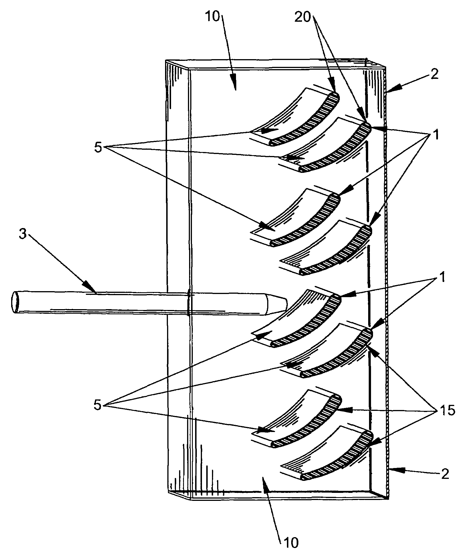
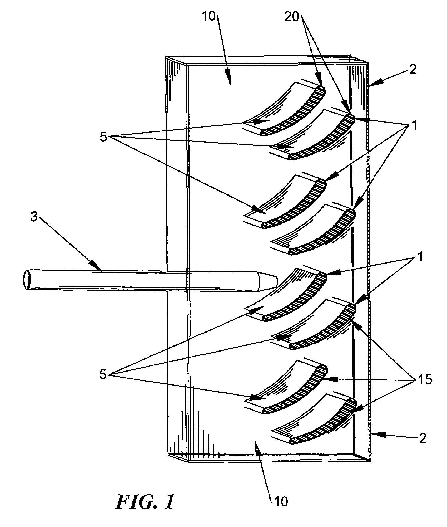
[0036]One of the limitations of lightweight armor is that by its very nature it has a low capacity to absorb and dissipate large amounts of heat and kinetic energy. Shaped-charge and high-explosive fragmenting weapons produce both high heat and high kinetic energy. As the charge or fragments slide along or penetrate the armor along the path 3 some of the kinetic energy is converted into heat, melting or vaporizing the impacted armor materials. It is preferable to deflect the jet stream or fragments rather than attempting to stop it. Current ceramic armor systems that are most effective utilize sloped plates to accomplish this. Ceramics can withstand the high energy loads, but they are heavy and brittle.

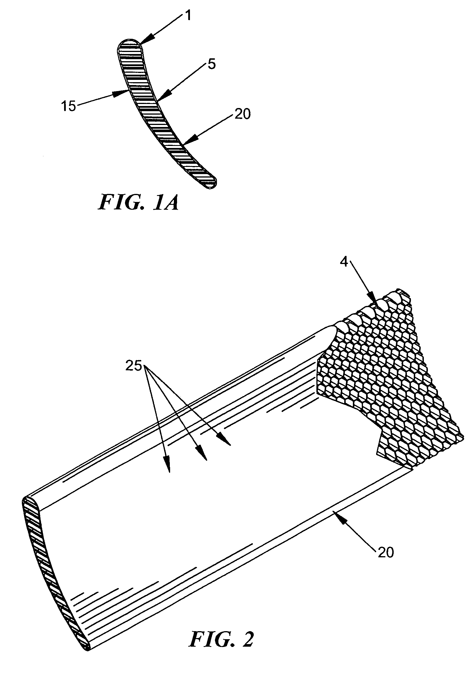
[0037]The invention utilizes a complementary mixture of materials to provide greater thermal capacity and friction resistance to thin metallic outer sheets used to construct lightweight deflecting armor components. Referring to FIG. 1, the invention consists of multiple layers of alum...


PUM


Abstract

A light-weight armor system for retrofitting onto light vehicles, such as HMMWVs, trucks, or helicopters, or incorporating into a vehicle to protect against HEAT or high explosive warheads. The armor system comprises multiple layers of a thin metal film. The front side of the thin metal sheet facing away from the vehicle is coated with a layer of zirconium nanoparticles and imprinted with a network of hollow packets filled with water and sealed. The back side of the thin metal sheet is coated with a layer of potassium bicarbonate powder. The multiple layers of metal film are imbedded in a matrix of composite foam to form a honeycomb structure that can be retrofitted onto light vehicles or used in new designs.

Description

RELATED APPLICATION DATA[0001]This application is related to Provisional Patent Application Ser. No. 60 / 579,882 filed on Jun. 15, 2004, and priority is claimed for this earlier filing under 35 U.S.C. § 120. The Provisional patent application is also incorporated by reference into this utility patent application.TECHNICAL FIELD OF THE INVENTION[0002]A light weight armor system for protecting general purpose, support military vehicles.BACKGROUND OF THE INVENTION[0003]All combat combines both defense and offense. However the traditional battlefield has almost always had a safe rear area to provide for the fighting forces. Current weaponry and support vehicles have been designed following this age old pattern: The fighting equipment and men defend the support equipment and men. Armored vehicle technology has been exclusively the domain of the Armored Fighting Vehicle. Armored fighting vehicles (AFVs), both tanks and armored personnel carriers (APCs), first saw limited use in World War I...

Claims


Application Information

Patent Timeline
Patent Type & Authority Patents(United States)
IPC IPC(8): F41H5/007
CPCF41H5/007F41H5/023F41H5/0442
Inventor MUNSON, JR., DAVID MURRAY
Owner FOI GRP
Why Eureka
Try Eureka