Method and system of MR imaging with simultaneous fat suppression and T1 inversion recovery contrast

a technology of mr imaging and fat suppression, applied in the field of diagnostic imaging, can solve the problems of affecting the diagnosis of lesions and other pathologies, affecting the detection of lesions, and affecting the detection accuracy of lesions, so as to achieve the suppression of pericardial fat, suppress signal, and enhance the time-course of lesions. remarkable

Active Publication Date: 2008-01-29
GENERAL ELECTRIC CO
View PDF12 Cites 35 Cited by
  • Summary
  • Abstract
  • Description
  • Claims
  • Application Information

AI Technical Summary

Benefits of technology

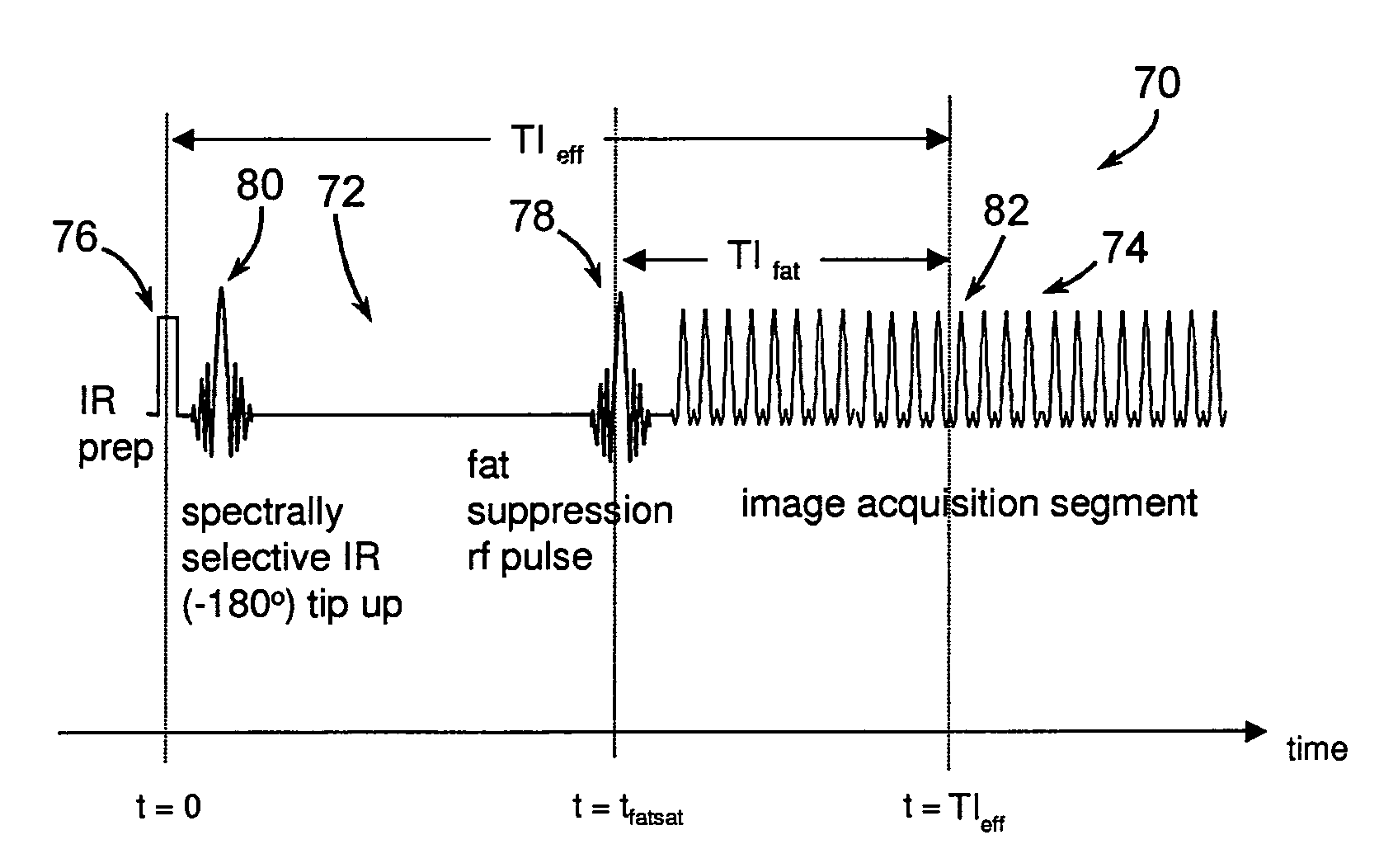
[0014]The present invention is directed to a pulse sequence for fat suppression with T1-weighted imaging. The pulse sequence is particularly beneficial in abdominal imaging where the time-course enhancement of lesions can be more remarkable without the high signal from abdominal fat masking small lesions. The invention is also particularly applicable to cardiac imaging and the suppression of pericardial fat that can otherwise affect the identification of epicardial margins of an infarcted zone or obscure the true extent of myocardial enhancement in patients with myocarditis. Moreover, the present invention is beneficial in suppressing signal from the pericardial fat that may obscure enhancement of the thin right ventricular myocardial wall in cases where the primary left ventricular myocardial infarction involves the right ventricular myocardium.
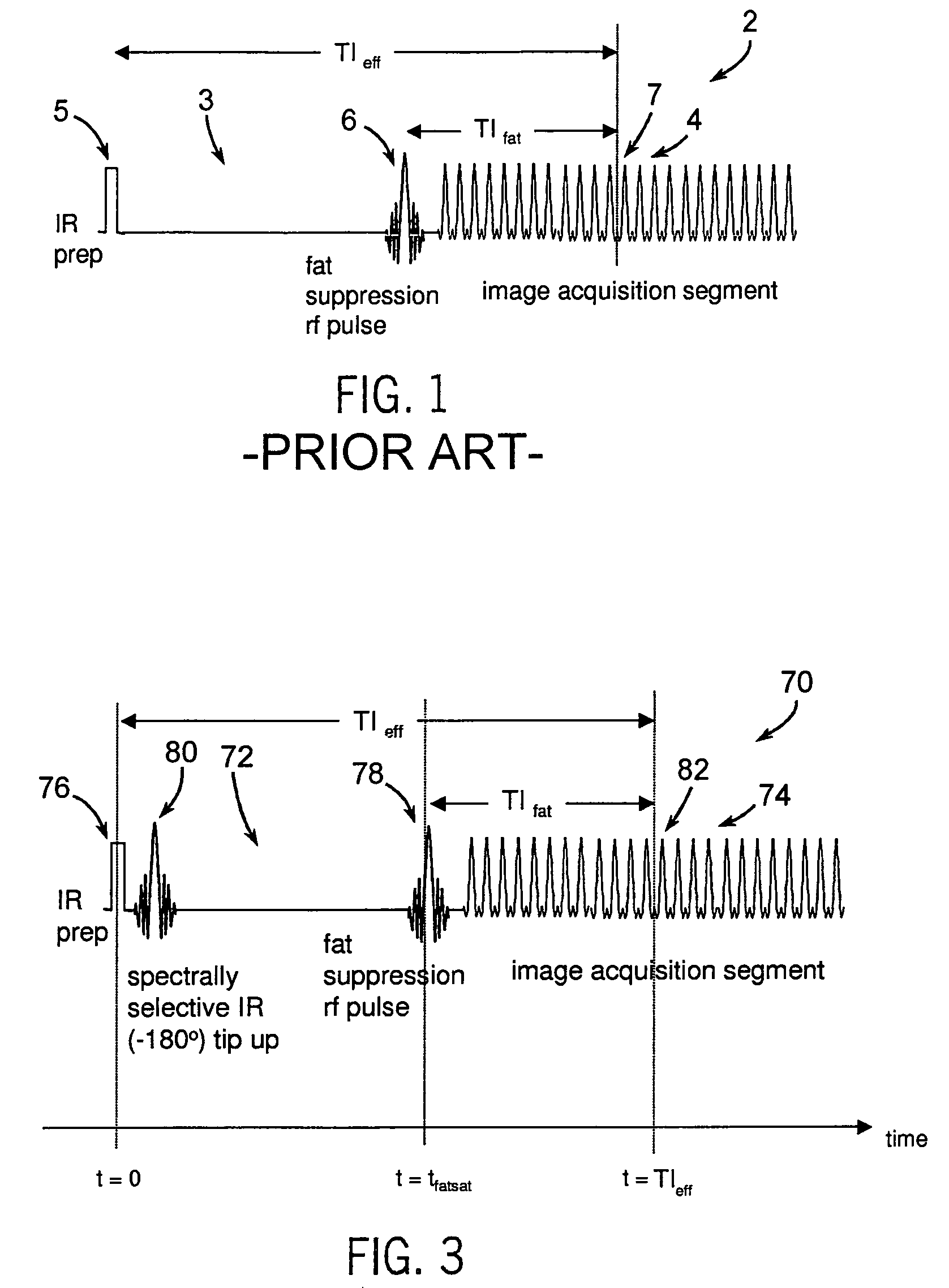
[0015]The pulse sequence is generally constructed to have a non-spectrally selective IR pulse that is played out immediately before a spectrally selective IR tip-up pulse. Thereafter, a fat suppression RF pulse is played out followed by the acquisition of fat-suppressed MR data. The pulse sequence maintains T1 contrast by not perturbing the non-fat signals from the IR preparation. The pulse sequence also ensures that the blood pool signal is homogeneously suppressed from the non-spectrally selective IR RF pulse. The pulse sequence also allows for increased fat suppression and provides flexibility for adjustment of the degree of fat suppression without affecting the view acquisition order for the image acquisition segment.

Problems solved by technology

A potential drawback of IR magnetization preparation is that data acquired from fat can cause a relatively bright signal to appear in the image due to the shorter T1 time of fat relative to other tissues.
This can complicate identification of lesions and other pathologies.
This can be particularly problematic for myocardial delayed enhancement (MDE) imaging as well as abdominal imaging where contrast-enhanced lesions are iso-intense with fat.
This leads to increased motion-related artifacts from ghosting of fat from the chest wall if the patient is unable to maintain a breath-hold or possibly more significant aliasing artifacts from fat within the shoulder when fields-of-view (FOVs) are small.
Furthermore, bright signal from pericardial fat may obscure proper identification of enhancing infarcted tissue over suppressed myocardium, which may be particularly problematic in regions of thinned myocardium such as in areas of chronic infarction or the right ventricle.
A disadvantage of this imaging technique for fat suppression is that it is dependent upon the longitudinal magnetization of fat being nulled at TIfat from the fat suppression RF pulse.
As the time is dependent on Mz,fat, it can be difficult to determine a solution for TIfat or that the solution changes from patient to patient, depending on the variation in Mz,fat according to Eqn. 2. As such, this conventional approach is not reliable for fat suppression in an IR T1-weighted acquisition.
This is because, depending on the TI used and other sequence parameters, there may not be an optimal TIfatsat to null fat without having to change the primary TI time.
A drawback of this double spectrally selective IR scheme is that if there is substantial magnetic field inhomogeneity, blood outside the imaged slice may be not sufficiently inverted.

Method used


Image

  • Method and system of MR imaging with simultaneous fat suppression and T1 inversion recovery contrast
  • Method and system of MR imaging with simultaneous fat suppression and T1 inversion recovery contrast
  • Method and system of MR imaging with simultaneous fat suppression and T1 inversion recovery contrast

Examples


Embodiment Construction

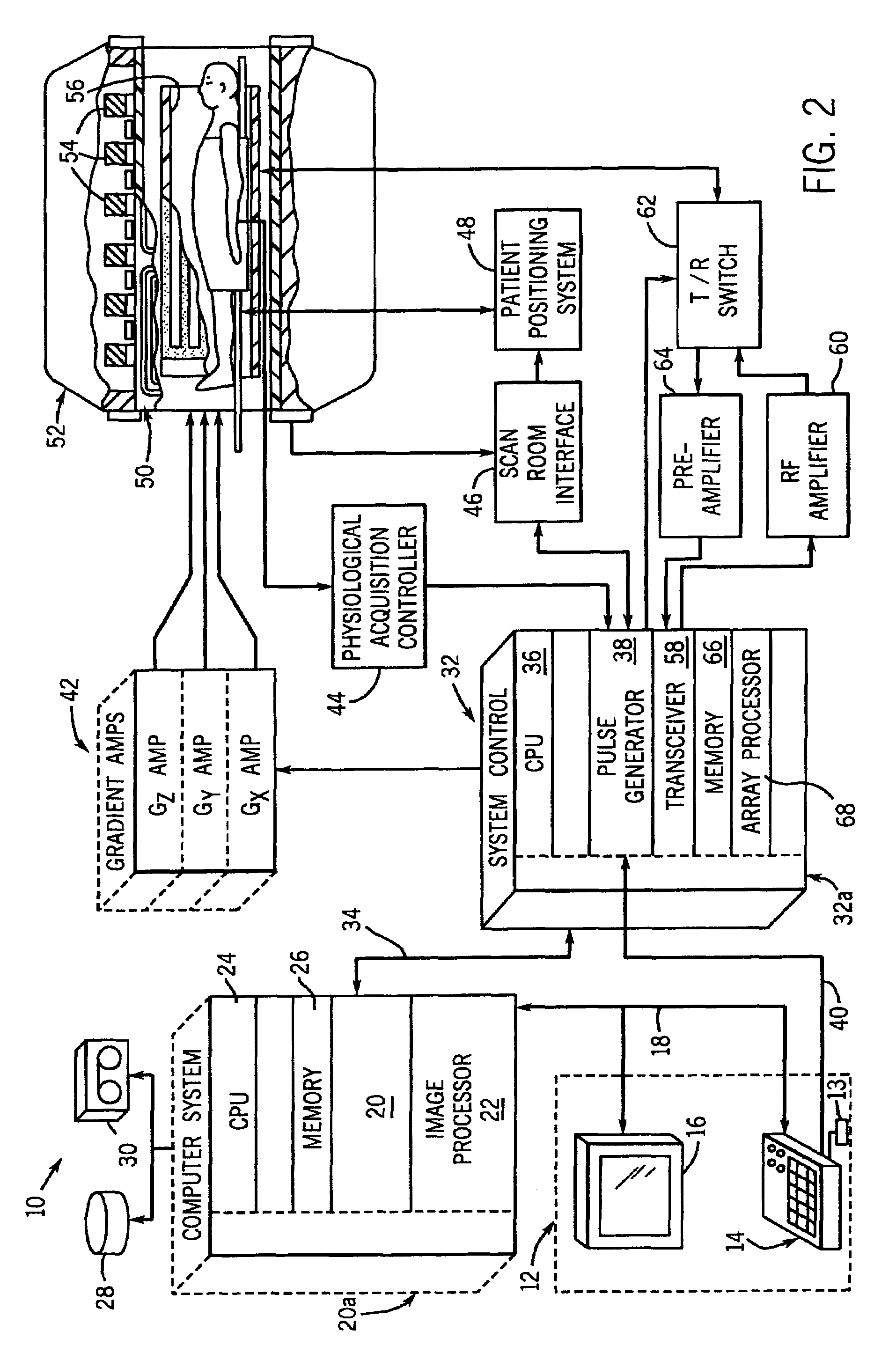
[0030]Referring to FIG. 2, the major components of an MR imaging system 10 incorporating the present invention are shown. The operation of the system is controlled from an operator console 12 which includes a keyboard or other input device 13, a control panel 14, and a display screen 16. The console 12 communicates through a link 18 with a separate computer system 20 that enables an operator to control the production and display of images on the display screen 16. The computer system 20 includes a number of modules which communicate with each other through a backplane 20a. These include an image processor module 22, a CPU module 24 and a memory module 26, known in the art as a frame buffer for storing image data arrays. The computer system 20 is linked to disk storage 28 and tape drive 30 for storage of image data and programs, and communicates with a separate system control 32 through a high speed serial link 34. The input device 13 can include a mouse, joystick, keyboard, track ba...


PUM


Abstract

A method and system for fat suppression with T1-weighted imaging includes a pulse sequence generally constructed to have a non-spectrally selective IR pulse that is played out immediately before a spectrally selective IR tip-up pulse. Thereafter, a fat suppression RF pulse is played out followed by the acquisition of fat-suppressed MR data. The pulse sequence maintains T1 contrast by not perturbing the non-fat signals from the IR preparation. The pulse sequence also ensures that the blood pool signal is homogeneously suppressed from the non-spectrally selective IR RF pulse. The pulse sequence also allows for increased fat suppression and provides flexibility for adjustment of the degree of fat suppression without affecting the view acquisition order for an image acquisition segment.

Description

BACKGROUND OF THE INVENTION[0001]The present invention relates generally to diagnostic imaging and, more particularly, to a method and system of achieving simultaneous fat suppression and T1 inversion recovery contrast in magnetic resonance (MR) imaging.[0002]When a substance such as human tissue is subjected to a uniform magnetic field (polarizing field B0), the individual magnetic moments of the spins in the tissue attempt to align with this polarizing field, but precess about it in random order at their characteristic Larmor frequency. If the substance, or tissue, is subjected to a magnetic field (excitation field B1) which is in the x-y plane and which is near the Larmor frequency, the net aligned moment, or “longitudinal magnetization”, MZ, may be rotated, or “tipped”, into the x-y plane to produce a net transverse magnetic moment Mt. A signal is emitted by the excited spins after the excitation signal B1 is terminated and this signal may be received and processed to form an im...

Claims


Application Information

Patent Timeline
Patent Type & Authority Patents(United States)
IPC IPC(8): G01V3/00
CPCG01R33/4828G01R33/56G01R33/5601G01R33/5602G01R33/5607
Inventor FOO, THOMAS K. F.
Owner GENERAL ELECTRIC CO
Why Eureka
Try Eureka