Power limiting circuit

a power limit and circuit technology, applied in the field of power limit circuits, can solve the problems of reducing limiting power using the window function, and affecting the accuracy so as to reduce power distribution, increase the precision of peak signal suppression, and ensure the effect of signal spectrum

Active Publication Date: 2013-05-21
NEC CORP +1
View PDF17 Cites 3 Cited by
  • Summary
  • Abstract
  • Description
  • Claims
  • Application Information

AI Technical Summary

Benefits of technology

[0011]In view of the foregoing, this invention seeks to provide a power limiting circuit having a feature of suppressing the radiation level outside a desired frequency band within a permissible range, and suppressing a loss of average power and a loss of backoff as much as possible, in particular a feature of suppressing the radiation level outside a desired frequency band as compared to the conventional art. Further, this invention seeks to provide a power limiting circuit in which the operation speed of the limiting circuit is lowered to reduce power consumption as compared to the related art.
[0013]According to this invention, the maximum value is detected to calculate a peak value of a signal in advance, thereby increasing the precision of peak signal suppression for a transmission signal, and the peak signal to be subtracted is subjected to the band limitation, thereby suppressing the peak signal without degrading a band outside the transmission spectrum band. Further, when the peak signal to be subtracted is subjected to the band limitation, the attenuation amount is controlled for each carrier, which makes it possible to control the ratio of distribution among the carriers and reduce power distribution to a carrier with strict standards. Therefore, this invention provides at least one of the following effects.
[0014]The first effect is that, when the peak signal is suppressed with respect to average power, the signal spectrum is not deteriorated. The reason is that the peak signal to be subtracted is subjected to the same band limitation as the input signal and accordingly the out-of-band spectrum is not generated because the signals in which the same band limitation is imposed are added or subtracted.
[0015]The second effect is that the provision of the means for varying, depending on the band, the ratio of distributing the peak signals to be subtracted makes it possible to collect the peak signals into a band with relaxed standards so as to reduce the influence on a band with strict standards.
[0016]The third effect is that the peak signal at a subsequent stage is predicted to suppress the operation speed for peak suppression of this invention. Suppressing the operation speed is equivalent to suppressing the circuit size and hence contributes to reduced power consumption.
[0017]The fourth effect is that the maximum value of the output signal is suppressed to reduce power consumption of a power amplifier which is required for a system embedding the power amplifier at a subsequent stage, to thereby contribute to reduced power consumption of the overall device.

Problems solved by technology

The related art that limits power using the window function suffers from a problem of degradation in frequency spectrum or error vector magnitude (EVM) of the transmission signal.
It can be therefore understood that the related art that limits power using the window function causes distortion in transmission frequency spectrum.
The distorted transmission spectrum affects signals in adjacent channels, causing degradation in receiving characteristics.
This leads to a problem that the circuit size is increased or a problem that the operation speed becomes faster to increase power consumption.
Further, the band is uniformly limited, which also makes it impossible to collect the peak signals into a carrier with relaxed standards in the multi-carrier case.

Method used


Image

  • Power limiting circuit
  • Power limiting circuit
  • Power limiting circuit

Examples


Embodiment Construction

[0047]Next, referring to the drawings, embodiments of this invention are described in detail.

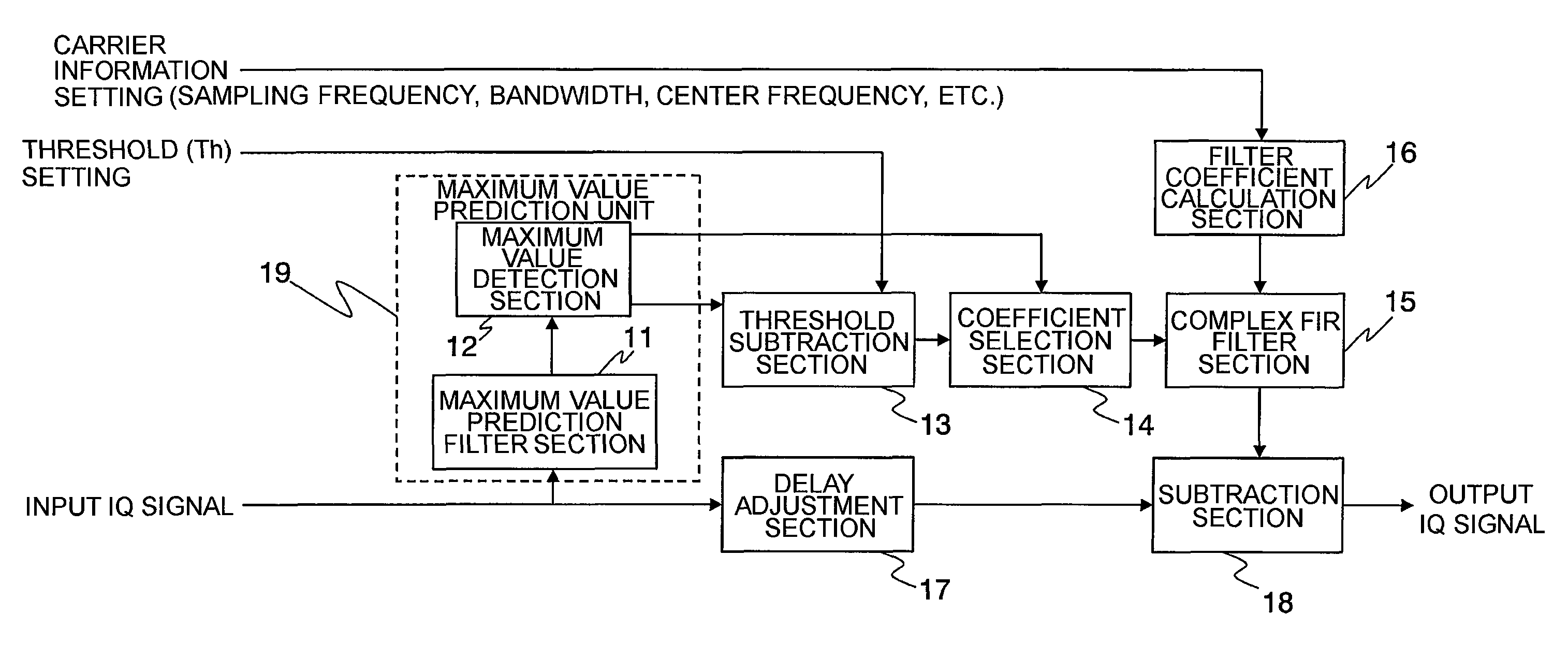
[0048]FIG. 1 is a block diagram illustrating a configuration of a power limiting circuit according to a first embodiment of this invention.

[0049]The illustrated power limiting circuit is a power limiting circuit for outputting an input signal by limiting a maximum instantaneous power value of the input signal to a predetermined power value or less. The power limiting circuit includes a branch section that branches an input IQ signal which is quantized at a first sampling rate, a maximum value prediction filter section 11 that interpolates one of the branched input signals at a second sampling rate higher than the first sampling rate, a maximum value detection section 12 that outputs a maximum value of the signal interpolated by the maximum value prediction filter section 11 and a time detection position thereof every constant period corresponding to the first sampling rate, a threshold subtr...


PUM


Abstract

A power limiting circuit includes: a maximum value prediction filter section (MVPFS) interpolating data of one branched digital input signal; a maximum value detection section detecting maximum value of an output of the MVPFS and a time detection position thereof every constant period; a threshold subtraction section subtracting a threshold from detected maximum value and outputting a peak signal (zero when the subtraction result is negative); a coefficient selection section weighting the peak signal according to time detection position; a complex filter section limiting the weighted peak signal within a band of the input signal; a filter coefficient calculation section calculating filter coefficients of the complex filter section; a delay adjustment section delaying another of the branched input signals by a time period required for calculating the band-limited peak signal; and a subtraction section subtracting the band-limited peak signal from the other of the branched input signals subjected to delay.

Description

TECHNICAL FIELD[0001]This invention relates to a power limiting circuit, and more particularly, to a circuit which puts a limitation on power to be input to a transmission power amplifier (power amplifier) or the like provided in a digital high-speed wireless communication system in the field of digital signal processing implemented by an application specific integrated circuit (ASIC) or a microprocessor.BACKGROUND ART[0002]In recent years, in the field of digital high-speed wireless communication systems, in order to meet the demands of the market for improved efficiency of frequency band usage and high-speed data communications, high-efficiency multiplexing schemes, such as code division multiple access (CDMA) and orthogonal frequency division multiplexing (OFDM), have been widely employed. Those schemes have a feature that a plurality of carriers and codes are multiplexed upon generation of a transmission signal to cause instantaneous power (peak factor or crest factor) which is ...

Claims


Application Information

Patent Timeline
Patent Type & Authority Patents(United States)
IPC IPC(8): H03L5/00
CPCH03F1/3223H03F3/195H03F3/245H04B1/707H03F2200/336H03F2200/451H04B2201/70706
Inventor SATO, HIROTAKAKONO, KIMIHIKODOI, YOSHIAKIKUSHIOKA, YOICHI
Owner NEC CORP
Why Eureka
Try Eureka