RF integrated circuit comprising a frequency synthesizer not very sensitive to injection locking

a frequency synthesizer and integrated circuit technology, applied in the direction of digital transmission, pulse automatic control, modulation, etc., can solve the problems of complex implementation, phase-locked loop not able to completely remove spurious components, deteriorating the performance of the latter, etc., to achieve the injection locking effect of such rf circuits, the effect of reducing the effect of the injection locking

Inactive Publication Date: 2008-01-29
ST ERICSSON SA
View PDF10 Cites 15 Cited by
  • Summary
  • Abstract
  • Description
  • Claims
  • Application Information

AI Technical Summary

Benefits of technology

[0023]According to principles of the present invention, the injection locking effect in such RF circuits, is reduced.
[0031]Indeed, given that, in such a frequency synthesizer, the frequency step of the main signal F1 varies according to the frequency step of the auxiliary signal F2, it becomes possible to apply to the main frequency synthesizer a comparison signal having a high frequency compared to the classical 400 kHz, and to provide in the main frequency synthesizer a phase-locked loop having an extended bandwidth that is much higher than 1 / 10 of the frequency step of the auxiliary signal. Also, according to another aspect of the present invention, the frequency F2 of the auxiliary frequency synthesizer is chosen to be sufficiently far from the frequency F1 so as not to be sensitive to the spurious signals sent by the QAM modulator.

Problems solved by technology

FIG. 1 represents a radiotelephony RF integrated circuit in which the injection locking effect constitutes a fundamental problem for those skilled in the art.
It is well known that the involuntary injection of this spurious component into the core of the oscillator deteriorates the performances of the latter.
Indeed, the phase-locked loop does not manage to totally remove the spurious component that is therefore re-injected into the output signal of the voltage-controlled oscillator.
First of all, it is frequent for the voltage-controlled oscillator to be produced on a silicon microchip distinct from the one bearing the circuit TXCT. However, this solution is complex to implement and burdens the cost price of the RF circuits, which is passed on, at the end of the line, to the selling price of mobile telephones. Thus, the current tendency is, on the contrary, to integrate the oscillator into the silicon microchip bearing the transmission circuit TXCT. Integrating, onto the same silicon microchip, the output amplifier RFAMP that is not linear and constitutes a considerable source of high-amplitude spurious harmonics, is also considered.
Heterodyne systems are however complex and costly to produce, as are the additional mixers and filters.
The disadvantage of these two frequency synthesizers is that the output signal is supplied by a mixer, and that it is necessary to greatly filter the output of the mixer so as to only keep the useful frequency.
Such filtering most often requires an external component, and increases the cost price and the complexity of the RF integrated circuit.

Method used


Image

  • RF integrated circuit comprising a frequency synthesizer not very sensitive to injection locking
  • RF integrated circuit comprising a frequency synthesizer not very sensitive to injection locking
  • RF integrated circuit comprising a frequency synthesizer not very sensitive to injection locking

Examples


Embodiment Construction

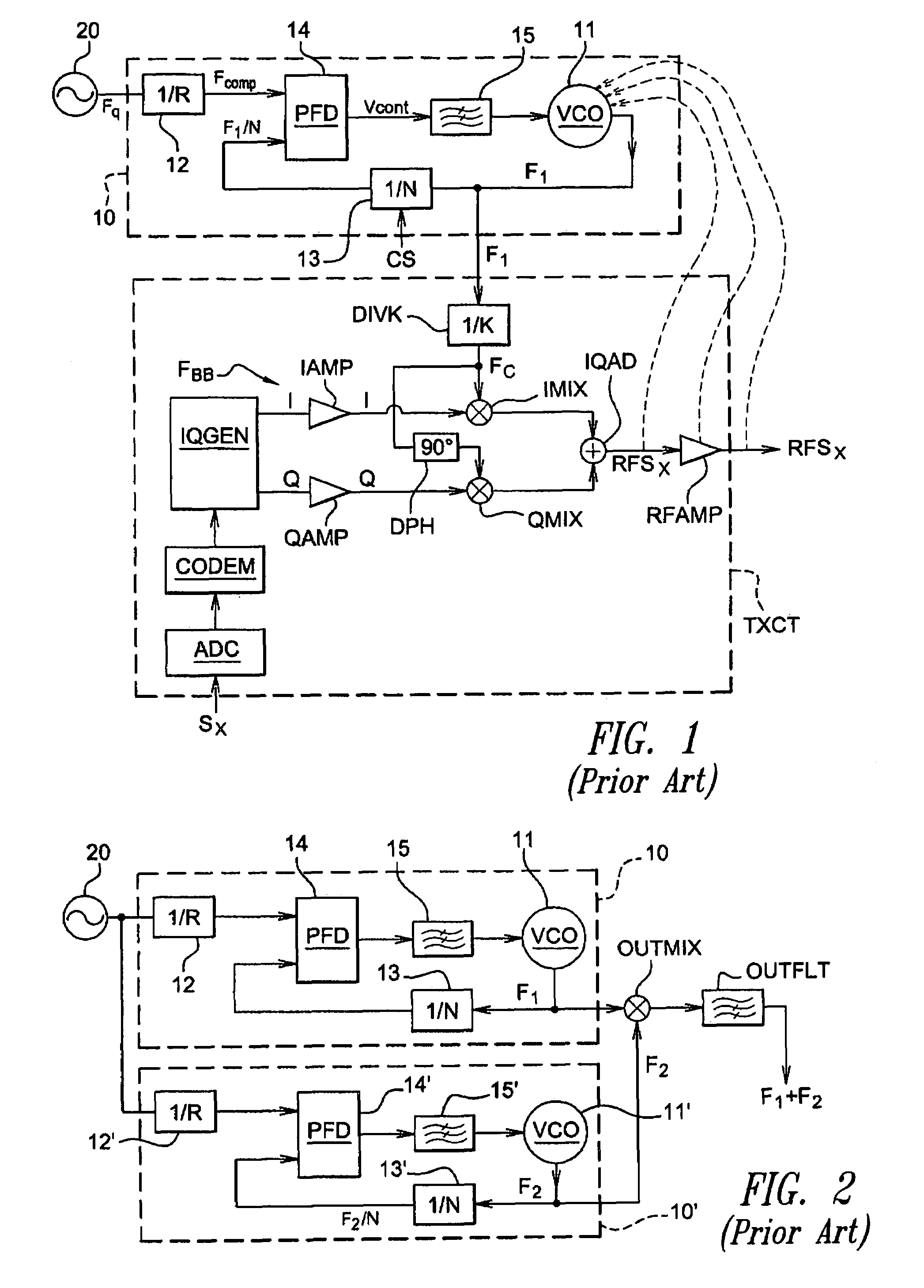
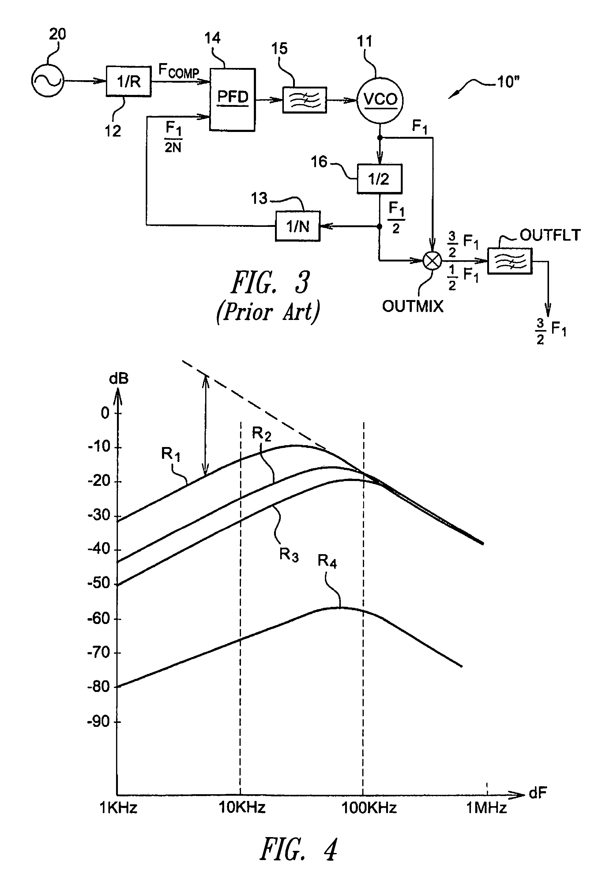
[0056]The curves R1, R2, R3 represented in FIG. 4 are the transfer functions of three phase-locked loops having respective bandwidths of 0-30 KHz, 0-60 KHz, and 0-100 KHz. These transfer functions represent the level of spurious signals at output of a frequency synthesizer 10 of the type described above in relation with FIG. 1, the spurious signals being sent by the QAM modulator (circuit TXCT).

[0057]The horizontal axis is graduated in differential frequency dF according to a logarithmic scale, i.e., the difference between the frequency of the spurious signal and the central frequency of the voltage-controlled oscillator. The vertical axis is graduated in relative level according to a logarithmic scale, i.e., the ratio between the level of the signal at the frequency considered and the level of the signal at the central frequency of the voltage-controlled oscillator.

[0058]The negative slope straight line represented in dotted lines represents the transfer function of the oscillator ...


PUM


Abstract

The present invention relates to an RF integrated circuit comprising a frequency synthesizer and a QAM modulator for modulating a baseband signal of frequency FBB, the frequency synthesizer supplying to the QAM modulator an output signal of frequency F1 adjustable with a frequency step ΔF1, for forming a carrier signal of the QAM modulator. According to the present invention, the frequency synthesizer is a Vernier effect frequency synthesizer comprising an auxiliary frequency synthesizer supplying an auxiliary signal of frequency F2 adjustable with a frequency step ΔF2 and a main frequency synthesizer having a phase-locked loop bandwidth at least two times higher than the frequency step ΔF2 of the auxiliary signal.

Description

FIELD OF THE INVENTION[0001]The present invention relates to frequency synthesizers comprising a voltage-controlled oscillator and a phase-locked loop.[0002]More particularly, the present invention relates to an RF integrated circuit comprising a frequency synthesizer and a QAM modulator for modulating a baseband signal of frequency FBB, the frequency synthesizer supplying to the QAM modulator an output signal of frequency F1 adjustable with a frequency step ΔF1, for forming a carrier signal of the QAM modulator.[0003]The present invention also relates to a method for reducing the injection locking effect in an RF integrated circuit comprising a frequency synthesizer and a QAM modulator for modulating a baseband signal of frequency FBB, the frequency synthesizer supplying to the QAM modulator an output signal of frequency F1 adjustable with a frequency step ΔF1, for forming a carrier signal of the QAM modulator, the injection locking effect being due to the injection of spurious sig...

Claims


Application Information

Patent Timeline
Patent Type & Authority Patents(United States)
IPC IPC(8): H04B1/40H03C3/06H03L7/23H04L27/36
CPCH03L7/23H04L27/362
Inventor RAMET, SERGETRIAIRE, PASCALJOUEN, PHILIPPE
Owner ST ERICSSON SA
Why Eureka
Try Eureka