
Reducing data acquisition, power and processing for photoplethysmography and other applications

a technology of photoplethysmography and data acquisition, applied in the field of reducing data acquisition, power and processing for photoplethysmography and other applications, can solve the problems of relatively high sampling rate and relatively intensive filtering, and achieve the effect of reducing the amount of data, processing and/or power

Inactive Publication Date: 2008-01-29
PACESETTER INC
View PDF9 Cites 63 Cited by
  • Summary
  • Abstract
  • Description
  • Claims
  • Application Information

AI Technical Summary

Benefits of technology

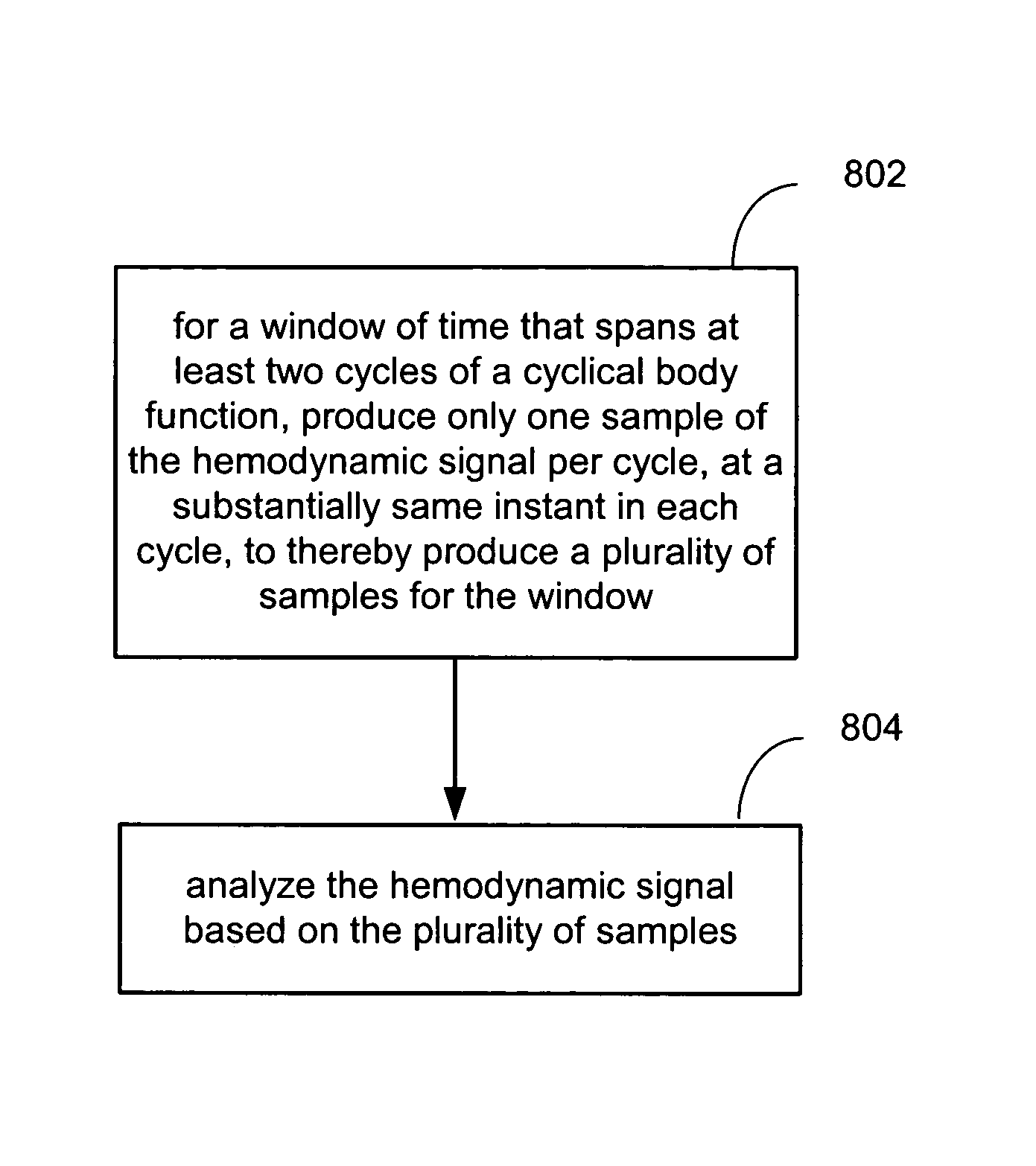
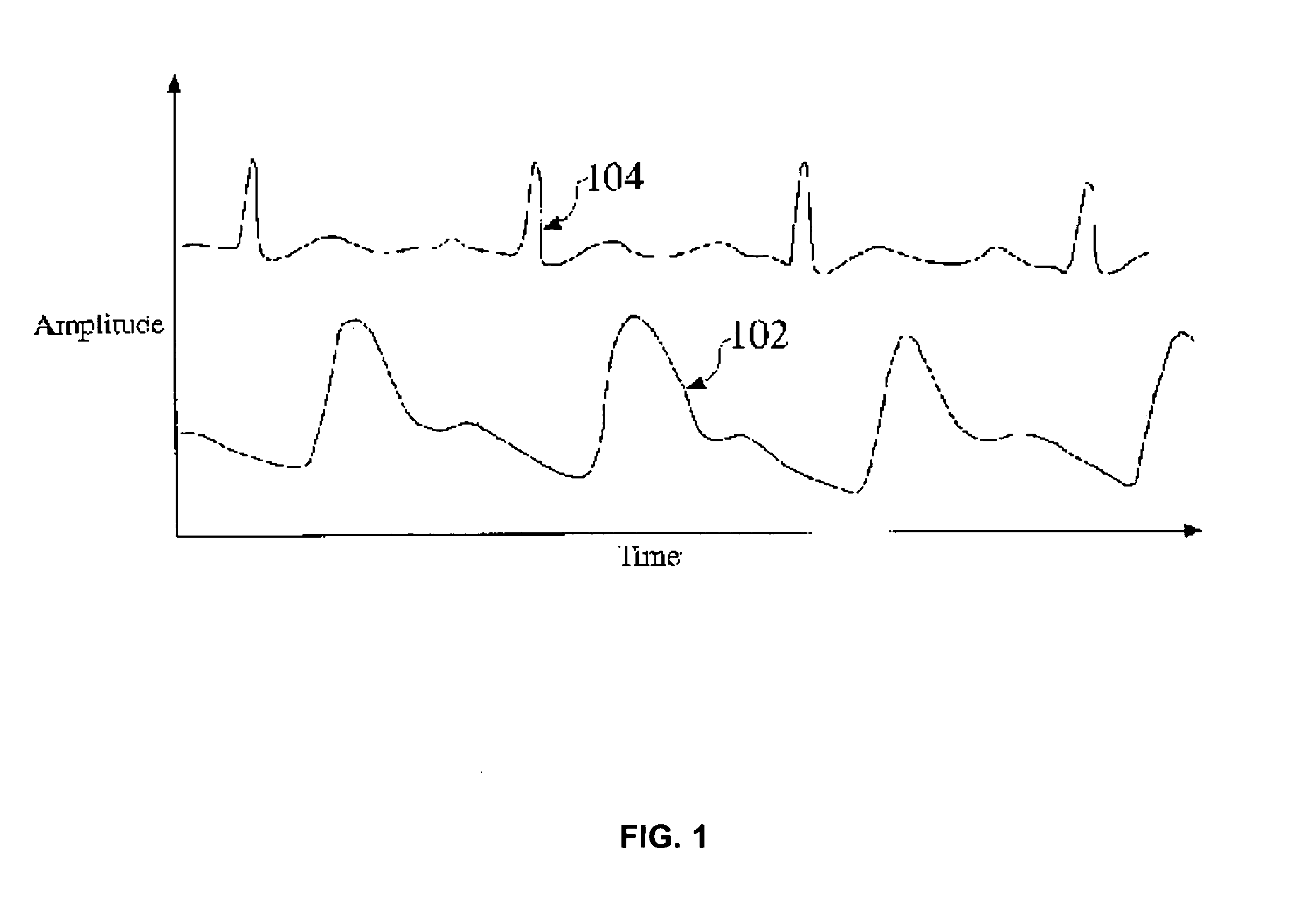
[0016]Embodiments of the present invention relate to methods, and systems (which can be implemented as devices) for reducing the amount of data, processing and / or power required to analyze hemodynamic signals such as photoplethysmography signals and arterial pressure signals.
[0021]Embodiments of the present invention also relate to reducing the amount of processing required to determine blood oxygen (O2) saturation levels.
[0023]In accordance with embodiments of the present invention, light of a first wavelength and light of a second wavelength are transmitted from a light source to a light detector (e.g., of a pulse oximetry device), such that a corresponding DC offset and pulse amplitude can be determined for light of the first wavelength received at the light detector and a corresponding DC offset and pulse amplitude can be determined for light of the second wavelength received at the light detector. An intensity of the transmitted light of the first wavelength is adjusted so that the DC offset for the light of the first wavelength received at the light detector is maintained at a substantially constant predetermined level. Similarly, the intensity of the transmitted light of the second wavelength is adjusted so that the DC offset for the light of the second wavelength received at the light detector is maintained at a substantially constant predetermined level. This enables an O2 saturation level to be determined based on a pulse amplitude determined for the light of the first wavelength received at the light detector and a pulse amplitude determined for the light of the second wavelength received at the light detector, without having to normalize the pulse amplitudes.
[0024]In accordance with an embodiment of the present invention, prior to high pass filtering, a first light signal and a second light signal are sampled to determine an estimate of each signal's DC offset. The first light signal is indicative of light of a first wavelength that is received at the light detector, and the second light signal is indicative of light of a second wavelength that is received at the light detector. Then, after high pass filtering, the first light signal and the second light signal are sampled to determine a pulse amplitude for each signal, wherein the sampling before high pass filtering is at a lower frequency than the sampling after high pass sampling, to thereby reduce the amount of data produced. Then, an O2 saturation level is determined based on the estimates of DC offset for the first and second light signals and the pulse amplitudes for the first and second light signals.

Problems solved by technology

This relatively high sampling rate and relatively intensive filtering consume battery power and processing resources.

Method used


Image

  • Reducing data acquisition, power and processing for photoplethysmography and other applications
  • Reducing data acquisition, power and processing for photoplethysmography and other applications
  • Reducing data acquisition, power and processing for photoplethysmography and other applications

Examples


Embodiment Construction

Exemplary Photoplethysmography Sensors

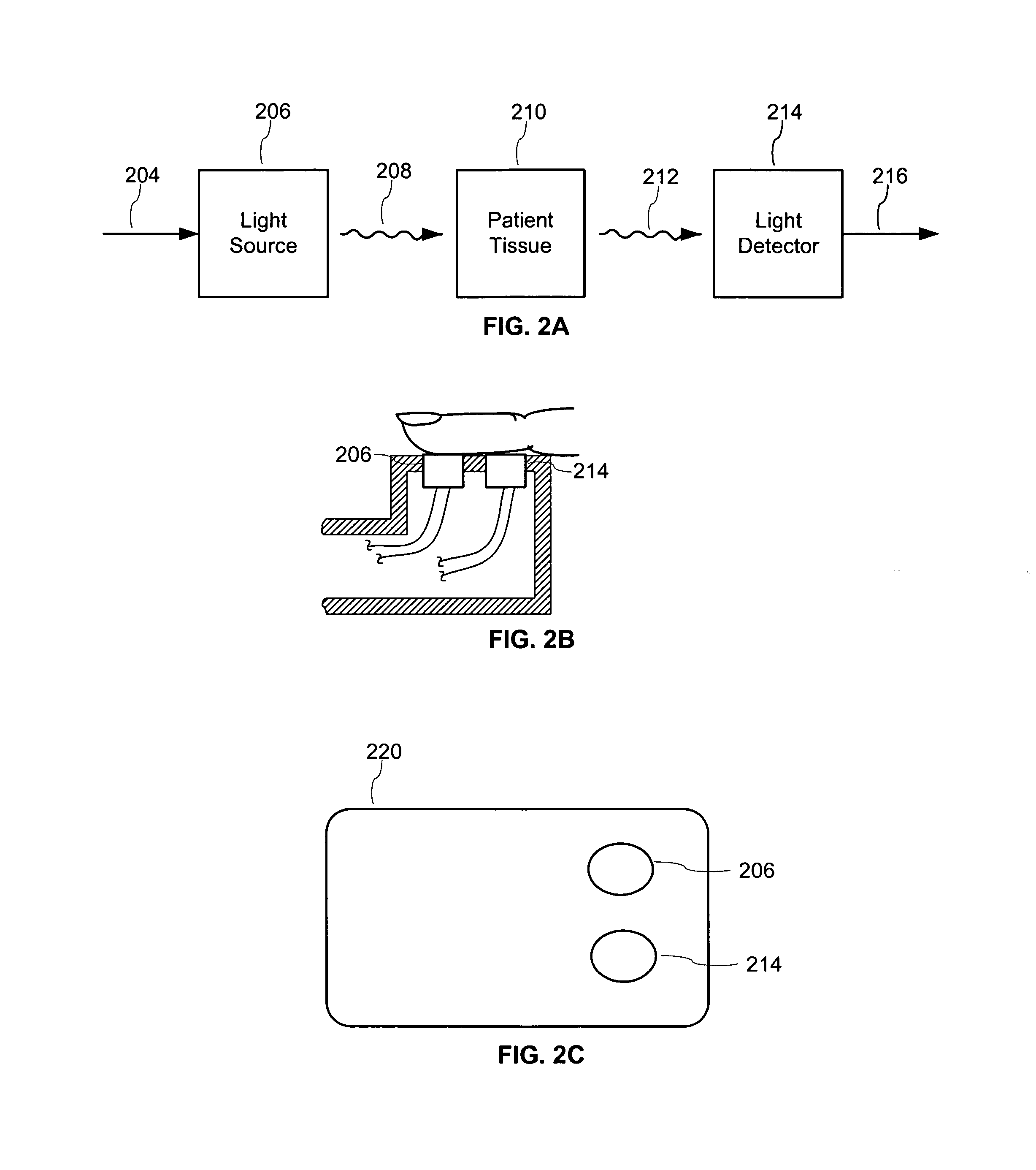
[0045]As mentioned above, a PPG sensor includes a light source and a light detector. FIGS. 3A and 3B illustrate exemplary light sources for use in the embodiments of the present invention. Referring first to FIG. 3A, exemplary light source 206 includes a single LED that produces light signal 208. The LED can be, for example, a model L53SRC / F red LED, or a model L53F3C infrared LED, both manufactured by Kingbright Corporation, City of Industry, Calif. Referring to FIG. 3B, a series of LEDs (e.g., LED1 and LED2) can be used to increase the amount of optical power in light signal 208. Separate LEDs can be used. Alternatively, dual emitter combination LEDs can be used, such as model DLED-660 / 905-LL5-2, manufactured by UDT Sensors, Inc., Hawthorne, Calif. In accordance with an embodiment, a pair of separately driven LEDs are used, where one of the LEDs is a red LED and the other is an infrared LED (which can be a near infrared LED), collectively allo...


PUM


Abstract

Methods, systems and devices are provided for reducing the amount of data, processing and / or power required to analyze hemodynamic signals such as photoplethysmography (PPG) signals, pressure signals, and impedance signals. Methods, systems and devices are also provided for reducing the amount of processing required to determine blood oxygen (O2) saturation levels.

Description

[0001]The captioned application claims the benefit of the earlier filing date of U.S. patent application Ser. No. 10 / 895,004 filed Jul. 19, 2004.FIELD OF THE INVENTION[0002]Embodiments of the present invention relate to reducing the amount of data, processing and / or power required to analyze hemodynamic signals such as photoplethysmography signals and arterial pressure signals.RELATED APPLICATIONS[0003]The present application is related to the following commonly invented and commonly assigned patent applications, each of which was filed on Jul. 19, 2004, and each of which is incorporated herein by reference:[0004]U.S. patent application Ser. No. 10 / 895,165 entitled “Reducing Data Acquisition, Power and Processing for Hemodynamic Signal Amplitude Detection”;[0005]U.S. patent application Ser. No. 10 / 894,962 entitled “Reducing Data Acquisition, Power and Processing for Hemodynamic Signal Sampling”; and[0006]U.S. patent application Ser. No. 11 / 734,861 which is a division of U.S. patent ...

Claims


Application Information

Patent Timeline
IPC IPC(8): A61N1/365
CPCA61B5/14551A61B5/1459A61B2560/0209A61N1/3621
Inventor TURCOTT, ROBERT G.
Owner PACESETTER INC
Learn More