

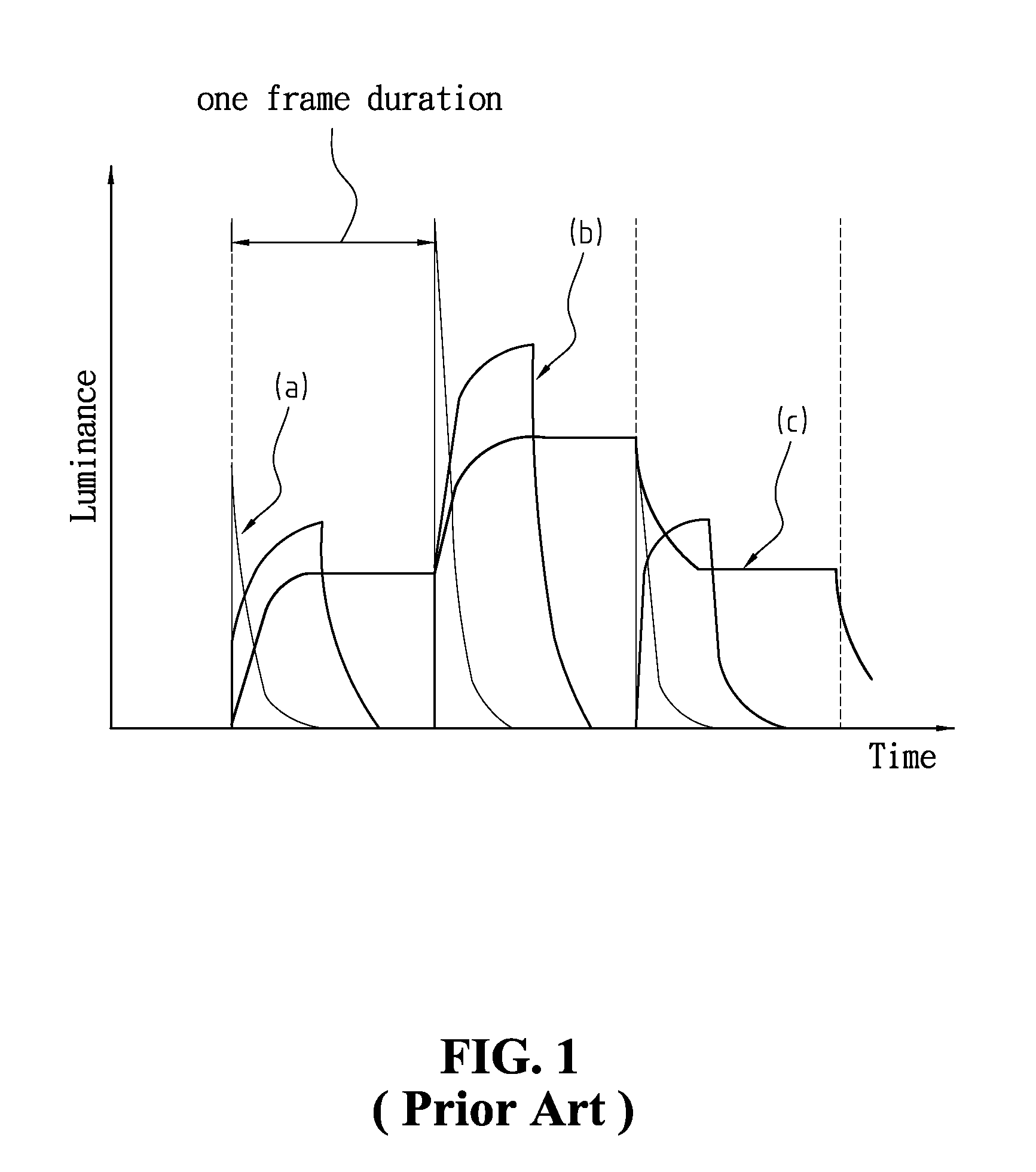
Method and device for simulating an impulse-type CRT display
a technology of impulse-type crt and display, which is applied in the direction of static indicating devices, instruments, analogue processes for specific applications, etc., can solve the problems of slower lcd gray scale optical response, obvious inferiority of image displaying effectiveness of conventional lcd televisions to that of crt televisions, drawbacks and limitations, etc., to save additional equipment costs, eliminate the effect of “after-image”
- Summary
- Abstract
- Description
- Claims
- Application Information
AI Technical Summary
Benefits of technology
Problems solved by technology
Method used
Image

Examples
embodiment 1
[0056]In the following analysis, please refer to FIGS. 3(a), 3(b) and FIGS. 4(a) to 4(e) as we explain the first embodiment of the present invention.
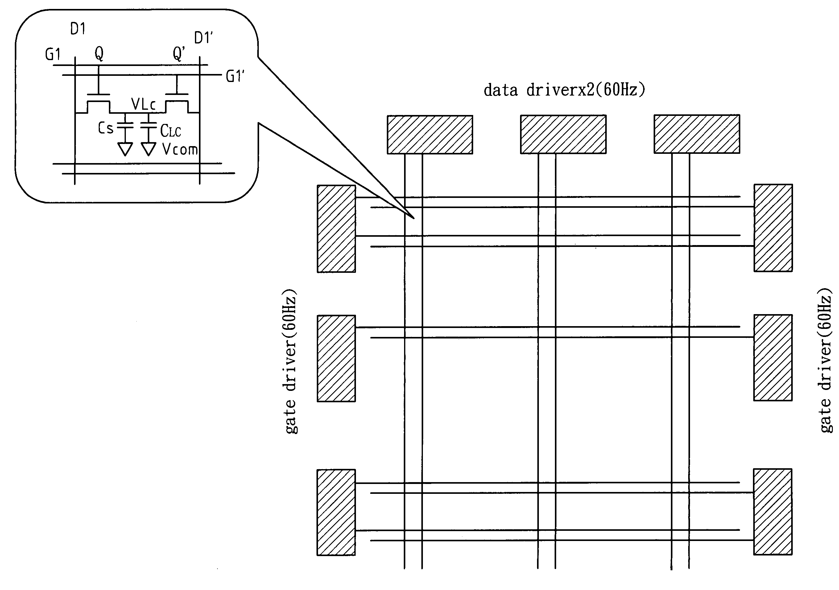
[0057]First, please refer to FIG. 3(a), which indicates: the pixel array formed by the cross points of a plurality of gate lines and data lines, and the driving circuit formed by a plurality of data drivers and gate drivers, according to the first embodiment of the present invention. And FIG. 3(b) represents the simulation device according to the first embodiment.
Simulation Device
[0058]According to FIGS. 3(a) and 3(b), the simulation device comprises: a first input control line (G1); a second input control line (G1′); a first input data line (D1); a second input data line (D1′); a first capacitor (CS); a second capacitor (CLS); a driving voltage output line; a first transistor (Q) comprising a first gate connected to the first input control line (G1), a first source connected to the first input data line (D1), and a first drain connecte...
embodiment 2
[0070]In the following analyses, please refer to FIGS. 5(a), 5(b) and FIGS. 6(a) to 6(g) as we explain the second embodiment of the present invention.
[0071]First, please refer to FIG. 5(a), which indicates: the pixel array formed by the cross points of a plurality of gate lines and data lines, and the driving circuit formed by a plurality of data drivers and gate drivers, according to the second embodiment of the present invention. And FIG. 5(b) represents the simulation device according to the second embodiment.
Simulation Device
[0072]According to FIGS. 5(a) and 5(b), the simulation device of the second embodiment comprises: a first input control line (G1); a second input control line (G1′); a first input data line (D1); a second input data line (D1′); a third input data line (D′); a fourth input data line (D); a fifth input data line (Ds); a first capacitor (CS); a second capacitor (CLS); a third transistor (Q3); a fourth transistor (Q4); a driving voltage output line; a first tran...
embodiment 3
[0083]In the following analyses, please refer to FIGS. 7(a), 7(b) and FIGS. 8(a) to 8(d) as we explain the third embodiment of the present invention.
[0084]First, please refer to FIG. 7(a), which indicates: the pixel array formed by the cross points of a plurality of gate lines and data lines, and the driving circuit formed by a plurality of data drivers and gate drivers according to the third embodiment of the present invention. And FIG. 7(b) represents the simulation device according to the third embodiment.
Simulation Device
[0085]According to FIGS. 7(a) and 7(b), the simulation device comprises: a first input control line (G1) connected to a first gate driver; a second input control line (G1′); a first input data line (D1); a first capacitor (CS); a second capacitor (CLS); a driving voltage output line; a first transistor (Q) having a gate connected to the first input control line (G1), a source connected to the first input data line (D1), and a drain connected to the driving volta...
PUM
 Abstract
Description
Claims
Application Information